RM27T0E
_51
Engine / Hybrid System
_053665
1GD-FTV ENGINE MECHANICAL
_0260521
CYLINDER BLOCK
A
1GD-FTV ENGINE MECHANICAL CYLINDER BLOCK REPLACEMENT
PROCEDURE

 1.REPLACE STRAIGHT PIN
- NOTICE:
-
It is not necessary to remove the straight pin unless it is being replaced.
a.
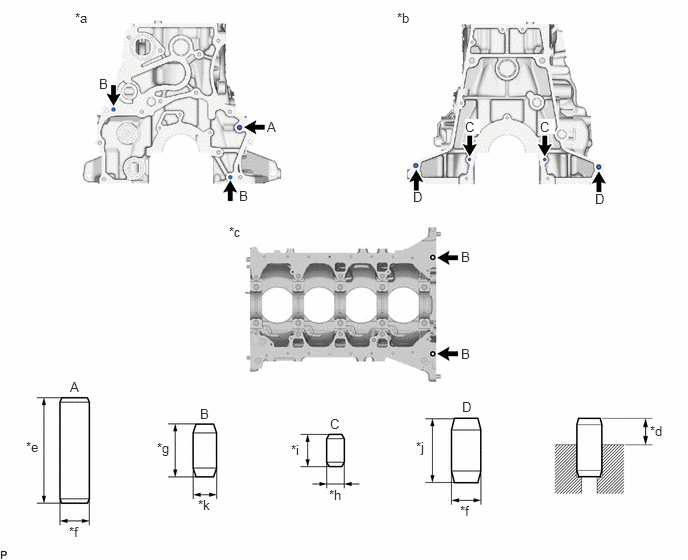
Remove the straight pin from the cylinder block sub-assembly.
b.
Using a plastic-faced hammer, tap in a new straight pin to the cylinder block sub-assembly.
0.781,0.104 0.969,0.26
0.188,0.156
10
false
*a
4.135,0.104 4.323,0.26
0.188,0.156
10
false
*b
2.385,2.333 2.573,2.49
0.188,0.156
10
false
*c
6.771,4.406 6.958,4.563
0.188,0.156
10
false
*d
0.271,4.573 0.458,4.729
0.188,0.156
10
false
*e
0.719,5.458 0.906,5.615
0.188,0.156
10
false
*f
1.635,4.583 1.833,4.792
0.198,0.208
10
false
*g
3.427,5.073 3.615,5.229
0.188,0.156
10
false
*h
3.031,4.604 3.219,4.76
0.188,0.156
10
false
*i
4.333,4.573 4.521,4.76
0.188,0.188
10
false
*j
2.063,5.177 2.25,5.333
0.188,0.156
10
false
*k
4.792,5.24 4.979,5.396
0.188,0.156
10
false
*f
0.729,3.948 0.885,4.104
0.156,0.156
10
false
A
2.083,4.229 2.24,4.385
0.156,0.156
10
false
B
3.438,4.333 3.594,4.49
0.156,0.156
10
false
C
4.813,4.156 4.969,4.313
0.156,0.156
10
false
D
2.781,1.24 2.938,1.396
0.156,0.156
10
false
A
1.031,0.792 1.177,0.948
0.146,0.156
10
false
B
4.844,1.24 5,1.396
0.156,0.156
10
true
C
4.302,1.969 4.458,2.125
0.156,0.156
10
false
D
2.49,1.958 2.646,2.115
0.156,0.156
10
false
B
6.198,1.99 6.354,2.146
0.156,0.156
10
false
D
5.625,1.24 5.781,1.396
0.156,0.156
10
true
C
4.802,2.594 4.958,2.75
0.156,0.156
10
false
B
4.802,3.604 4.958,3.76
0.156,0.156
10
false
B
| *a | Engine Front Side | *b | Engine Rear Side |
| *c | Engine Lower Side | *d | Protrusion Height |
| *e | 36 mm (1.42 in.) | *f | 10 mm (0.394 in.) |
| *g | 18 mm (0.709 in.) | *h | 6.0 mm (0.236 in.) |
| *i | 11 mm (0.433 in.) | *j | 22 mm (0.866 in.) |
| *k | 8.0 mm (0.315 in.) | - | - |
- Standard Protrusion Height:
Item Specified Condition Straight Pin A 18 to 20 mm (0.709 to 0.787 in.) Straight Pin B 8.0 to 10 mm (0.315 to 0.394 in.) Straight Pin C 4.0 to 6.0 mm (0.157 to 0.236 in.) Straight Pin D 10 to 12 mm (0.394 to 0.472 in.)
2.REPLACE RING PIN
- NOTICE:
-
It is not necessary to remove the ring pin unless it is being replaced.
a.
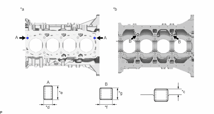
Remove the ring pin from the cylinder block sub-assembly.
b.
Using a plastic-faced hammer, tap in a new ring pin to the cylinder block sub-assembly.
0.678,0.223 0.862,0.378
0.185,0.155
10
*a
3.788,0.224 3.972,0.379
0.185,0.155
10
*b
6.085,2.978 6.270,3.133
0.185,0.155
10
*c
1.531,3.505 1.715,3.660
0.185,0.155
10
*d
1.972,3.007 2.157,3.162
0.185,0.155
10
*e
3.506,3.503 3.691,3.658
0.185,0.155
10
*f
3.97,3.026 4.155,3.217
0.185,0.191
10
*g
1.567,2.666 1.720,2.825
0.153,0.159
10
A
3.512,2.731 3.665,2.890
0.153,0.159
10
B
0.51,1.165 0.663,1.324
0.153,0.159
10
A
3.477,1.176 3.630,1.335
0.153,0.159
10
A
4.313,1.297 4.466,1.455
0.153,0.159
10
B
5.962,1.317 6.115,1.476
0.153,0.159
10
B
| *a | Engine Upper Side | *b | Engine Lower Side |
| *c | Protrusion Height | *d | 10.5 mm (0.413 in.) |
| *e | 15 mm (0.591 in.) | *f | 13 mm (0.512 in.) |
| *g | 12 mm (0.472 in.) | - | - |
- Standard Protrusion Height:
Item Specified Condition Ring Pin A 5.5 to 7.5 mm (0.217 to 0.295 in.) Ring Pin B 5.0 to 7.0 mm (0.197 to 0.276 in.)