2TR-FE FUEL FUEL PUMP(for 5 Door) INSTALLATION
CAUTION / NOTICE / HINT
- HINT:
-
Perform "Inspection After Repairs" after replacing the fuel pump (See page Engine / Hybrid System>2TR-FE (ENGINE CONTROL)>SFI SYSTEM>INITIALIZATION).
PROCEDURE

 77020A
1.INSTALL FUEL SUCTION WITH PUMP AND GAUGE TUBE ASSEMBLY
Apply a light coat of gasoline or grease to a new gasket and install the gasket to the fuel tank sub-assembly.
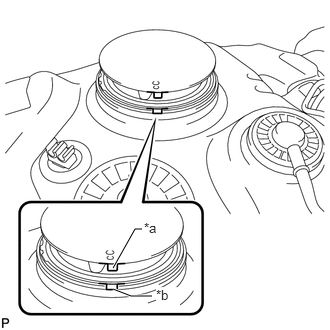
Align the protrusion of the fuel suction with pump and gauge tube assembly with the groove of the fuel tank sub-assembly.
| *a | Protrusion |
| *b | Groove |
- NOTICE:
-
Be careful not to bend the arm of the fuel sender gauge assembly.
Install the fuel suction with pump and gauge tube assembly to the fuel tank sub-assembly.
Put a new fuel pump gauge retainer on the fuel tank sub-assembly. While holding the fuel suction with pump and gauge tube assembly, tighten the retainer one complete turn by hand.
- HINT:
-
 2.281,0.927 2.688,0.5 2.688,0.5 2.781,0.5 true 2.417,0.938 2.771,0.938 true 2.792,0.833 3.063,1.094 0.271,0.26 10 true *a 2.792,0.406 3.042,0.667 0.25,0.26 10 true *b
-
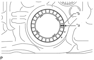
Make sure the start marks on the fuel pump gauge retainer and fuel tank sub-assembly are aligned and then tighten the fuel pump gauge retainer.
| *a | Start Mark (Fuel Tank Sub-assembly Side) |
| *b | Start Mark (Fuel Pump Gauge Retainer Side) |
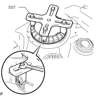
Set SST on the fuel pump gauge retainer.
- SST
- 09808-14030 (09808-01030, 09808-01040)
- HINT:
- ·
Hold the fuel suction with pump and gauge tube assembly upright by hand to ensure that the fuel suction tube gasket in not moved out of position.
·Engage the claws of SST securely with the fuel pump gauge retainer holes to secure SST.
·Install SST while pressing the claws of SST against the fuel pump gauge retainer (toward the center of SST).
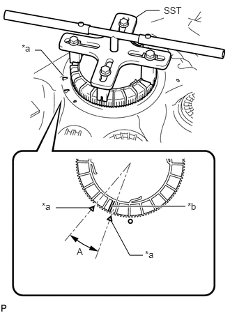
Using SST, tighten the fuel pump gauge retainer until the mark on the fuel pump gauge retainer is within range A on the fuel tank sub-assembly as shown in the illustration.
- SST
- 09808-14030 (09808-01010)
| *a | Fuel Tank Sub-assembly Side Mark |
| *b | Fuel Pump Gauge Retainer Side Mark |
- HINT:
-
Fit the tips of SST onto the ribs of the fuel pump gauge retainer.
77100U
2.INSTALL FUEL TANK SUB-ASSEMBLY