2TR-FE FUEL FUEL PUMP(for 5 Door) REASSEMBLY
CAUTION / NOTICE / HINT
- NOTICE:
-
Do not disconnect the hoses indicated in the illustration.
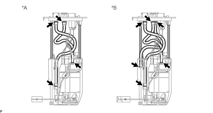 0.733,0.154 0.980,0.331 0.247,0.178 12 *A 3.747,0.154 3.994,0.331 0.247,0.178 12 *B
Text in Illustration *A for Single Tank Type *B for Double Tank Type
- HINT:
-
Perform "Inspection After Repairs" after replacing the fuel pump (See page Engine / Hybrid System>2TR-FE (ENGINE CONTROL)>SFI SYSTEM>INITIALIZATION).
PROCEDURE

 23221
1.INSTALL FUEL PUMP
- HINT:
-
Perform "Inspection After Repairs" after replacing the fuel pump (See page Engine / Hybrid System>2TR-FE (ENGINE CONTROL)>SFI SYSTEM>INITIALIZATION).
Connect the fuel pump wire harness connector to the fuel pump.
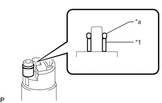
Apply a light coat of gasoline to a new O-ring. Then install the fuel pump spacer and O-ring to the fuel pump.
| *1 | Fuel Pump Spacer |
| *a | O-Ring |
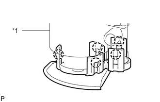
Attach the 5 claws to the claw holes to install the fuel pump to the fuel filter case.
| *1 | Fuel Filter Case |
77174
2.INSTALL NO. 1 FUEL SUCTION SUPPORT
Install the No. 1 fuel suction support and attach the 2 claws.
77131C
3.INSTALL NO. 1 FUEL SUB-TANK (for Single Tank Type)
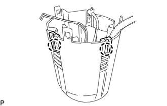
Attach the 2 claws to the claw holes to install the No. 1 fuel sub-tank.
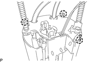
Attach the 3 claws to the claw holes.
Install the tube part to the No. 1 fuel sub-tank.
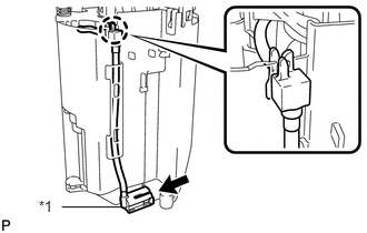
Attach the claw on the end of the tube to the claw hole. Install the tube to the 2 clamps on the No. 1 fuel sub-tank.
Connect the jet pump to the No. 1 fuel sub-tank.
| *1 | Jet Pump |
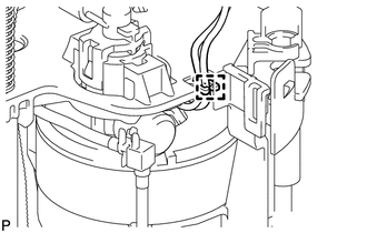
Attach the fuel pump wire harness clamp.
Connect the fuel pump connector.
77131C
4.INSTALL NO. 1 FUEL SUB-TANK (for Double Tank Type)
Attach the 2 claws to the claw holes to install the No. 1 fuel sub-tank.
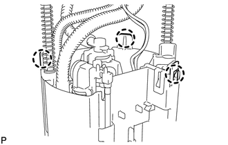
Attach the 3 claws to the claw holes.
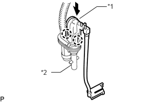
Apply a light coat of gasoline to a new O-ring. Then install the O-ring to the jet pump B.
| *1 | Jet Pump A |
| *2 | Jet Pump B |
Connect the jet pump A and attach the 2 claws.
Connect the jet pump labeled B to the No. 1 fuel sub-tank.
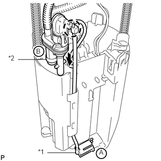
Attach the claw on the end of the tube to the claw hole.
| *1 | Jet Pump A |
| *2 | Jet Pump B |
Connect the jet pump labeled A to the No. 1 fuel sub-tank.
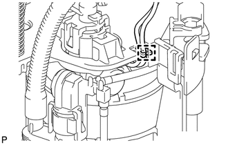
Attach the fuel pump wire harness clamp.
Connect the fuel pump connector.
83320
5.INSTALL FUEL SENDER GAUGE ASSEMBLY (for Single Tank Type)
83320B
6.INSTALL FUEL SENDER GAUGE ASSEMBLY (for Double Tank Type)