RM27T0E
_51
Engine / Hybrid System
_053672
1GR-FE EMISSION CONTROL
_0260604
AIR SWITCHING VALVE(for Bank 2)
A
1GR-FE EMISSION CONTROL AIR SWITCHING VALVE(for Bank 2) INSTALLATION
PROCEDURE

 25702
1.INSTALL NO. 2 EMISSION CONTROL VALVE SET
a.
Install the No. 2 emission control valve set with the 3 nuts.
- Torque:
- 21 N*m (214 kgf*cm, 15 ft.*lbf)
b.
0.438,1.125 0.5,1.125
0.5,1.125 0.656,0.771
true
1.188,0.188 1.094,0.188
1.094,0.188 0.917,0.719
true
2.417,0.052 2.594,0.219
0.177,0.167
10
false
*a
1.208,0.115 1.385,0.281
0.177,0.167
10
false
*2
3.156,0.531 3.333,0.698
0.177,0.167
10
false
*b
0.229,1.021 0.406,1.188
0.177,0.167
10
false
*1
2.938,0.823 3.188,0.969
0.25,0.146
10
false
60°
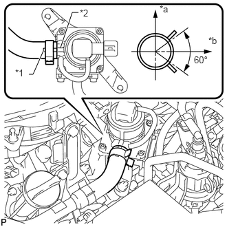
Align the paint mark with the projection and connect the No. 1 air hose.
| *1 | Paint Mark |
| *2 | Rib |
| *a | Upper |
| *b | LH Side |
- HINT:
-
Make sure the direction of the hose clamp is as shown in the illustration.
c.
Connect the No. 2 emission control valve set connector.
17362
2.INSTALL NO. 2 AIR TUBE
a.
2.958,0.188 2.875,0.188
2.875,0.188 2.813,0.385
false
2.813,1.01 2.646,1.01
2.646,1.01 2.479,0.927
false
2.833,0.917 3.01,1.073
0.177,0.156
10
false
*1
3.01,0.146 3.188,0.302
0.177,0.156
10
false
*2
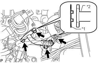
Install 2 new gaskets to the No. 2 air tube.
| *1 | New Gasket |
| *2 | No. 2 Air Tube |
b.
Install the No. 2 air tube with the 2 bolts and 2 nuts.
- Torque:
- 10 N*m (102 kgf*cm, 7 ft.*lbf)
25860
3.INSTALL PURGE VSV
a.
Install the purge VSV (See page Engine / Hybrid System>1GR-FE (EMISSION CONTROL)>PURGE VALVE>INSTALLATION).