RM27T0E
_51
Engine / Hybrid System
_053673
1KD-FTV EMISSION CONTROL
_0260615
VACUUM REGULATING VALVE
G
1KD-FTV EMISSION CONTROL VACUUM REGULATING VALVE INSPECTION
CAUTION / NOTICE / HINT
- NOTICE:
-
Do not remove the electric vacuum regulating valve from the bracket.
PROCEDURE

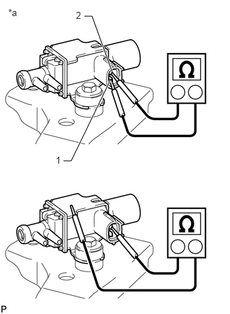
 1.INSPECT ELECTRIC VACUUM REGULATING VALVE ASSEMBLY (for EGR)
a.
1.26,0.24 1.375,0.24
1.375,0.24 1.677,1.073
true
0.948,2.396 1.063,2.396
1.063,2.396 1.646,1.198
true
0.833,2.302 0.938,2.448
0.104,0.146
10
false
1
1.135,0.146 1.24,0.292
0.104,0.146
10
false
2
0.125,0.104 0.333,0.281
0.208,0.177
10
false
*a
Measure the resistance according to the value(s) in the table below.
- Standard Resistance:
Tester Connection Condition Specified Condition 1 - 2 20°C (68°F) 11 to 13 Ω 1 - Body ground
2 - Body ground20°C (68°F) 10 MΩ or higher
| *a | Component without harness connected
(Electric Vacuum Regulating Valve) |
If the result is not as specified, replace the electric EGR control valve assembly.
b.
2.469,0.979 2.74,1.198
2.74,1.198 2.865,1.198
false
0.302,0.563 0.427,0.563
0.427,0.563 1.01,1.177
true
0.604,0.167 0.729,0.167
0.729,0.167 1.156,1.115
true
0.417,0.083 0.594,0.25
0.177,0.167
10
false
*1
1.198,2.667 1.375,2.833
0.177,0.167
10
false
*3
2.01,2.323 2.188,2.49
0.177,0.167
10
false
*4
2.896,1.125 3.073,1.292
0.177,0.167
10
false
*5
0.115,0.458 0.292,0.625
0.177,0.167
10
false
*2
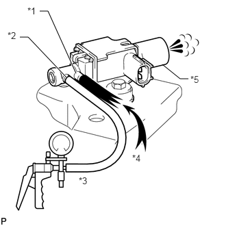
Check operation of the E-VRV.
i.
When a vacuum of 67 kPa (500 mmHg, 19.7 in.Hg) is applied to port F, check that air flows from port E to the filter.
| *1 | Port E |
| *2 | Port F |
| *3 | Vacuum |
| *4 | Air |
| *5 | Filter |
ii.
0.333,0.469 0.427,0.469
0.427,0.469 0.594,0.927
true
0.375,0.146 0.469,0.146
0.469,0.146 0.74,0.875
true
0.208,0.052 0.375,0.219
0.167,0.167
10
false
*1
0.135,0.375 0.302,0.542
0.167,0.167
10
false
*2
1.844,1.938 2.01,2.104
0.167,0.167
10
false
*3
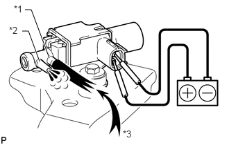
Apply battery voltage across terminals 1 and 2.
| *1 | Port E |
| *2 | Port F |
| *3 | Air |
iii.
Check that air flows from port E to port F.
If the result is not as specified, replace the electric EGR control valve assembly.