1GD-FTV INTAKE / EXHAUST EXHAUST MANIFOLD W/ TURBOCHARGER INSPECTION
PROCEDURE

 17201
1.VISUALLY CHECK TURBOCHARGER SUB-ASSEMBLY
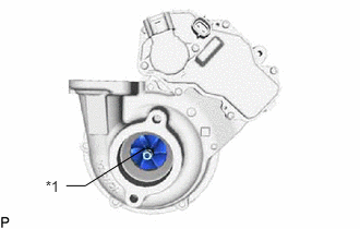
| *1 | Compressor Impeller |
Check for deformation and cracks in the compressor impeller on the intake side.
If the compressor impeller is cracked or deformed, replace the turbocharger sub-assembly.
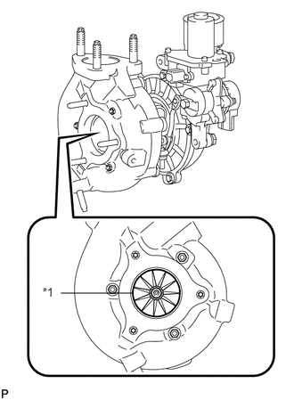
| *1 | Turbine Wheel |
Check for deformation and cracks in the turbine wheel on the exhaust side.
If the turbine wheel is cracked or deformed, replace the turbocharger sub-assembly.
17201
2.INSPECT AXIAL PLAY OF TURBINE SHAFT
Using a dial indicator, insert the needle of the dial indicator into the exhaust side of the turbine shaft.
- NOTICE:
-
Turbocharger sub-assembly and dial indicators are surely fixed when performing measurement.
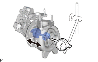
Move the turbine shaft in the axial direction and measure the axial play of the turbine shaft.
- Maximum axial play:
0.11 mm (0.00433 in.)
If the axial play is more than the maximum, replace the turbocharger sub-assembly.
17201
3.CHECK TURBINE SHAFT ROTATION
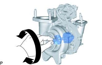
Rotate the turbine wheel on the exhaust side with your finger and check that it rotates smoothly.
- HINT:
-
Even if it takes a little effort to rotate the turbine wheel, this is not a problem.
If the turbine wheel does not rotate smoothly, replace the turbocharger sub-assembly.
17201
4.INSPECT TURBOCHARGER NOZZLE VANE CONTROL ACTUATOR
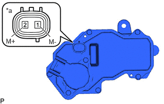
| *a | Component without harness connected
(Turbocharger Nozzle Vane Control Actuator) |
Measure the resistance according to the value(s) in the table below.
- Standard Resistance:
Tester Connection Condition Specified Condition 1 - 2 20°C (68°F) 1 to 100 Ω
- HINT:
-
The temperature indicated in "Condition" is the temperature of the turbocharger nozzle vane control actuator.
-
If the result is not as specified, replace the turbocharger nozzle vane control actuator.
Using a megohmmeter set to 500 V, measure the insulation resistance according to the value(s) in the table below.
- NOTICE:
-
Be sure to set the megohmmeter to 500 V when performing this test. Using a setting higher than 500 V can result in damage to the component being inspected.
- Standard Resistance:
Tester Connection Condition Specified Condition 1 (M-) - Body ground Always 10 MΩ or higher 2 (M+) - Body ground Always 10 MΩ or higher
- HINT:
-
If the result is not as specified, replace the turbocharger nozzle vane control actuator.