1GD-FTV STARTING STARTER(for 2.0 kW Type) REASSEMBLY
PROCEDURE

 28160
1.INSTALL STARTER ARMATURE ASSEMBLY
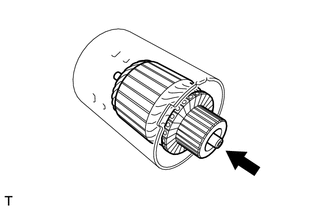
Install the starter armature assembly to the starter yoke assembly.
- NOTICE:
-
The magnet of the starter yoke assembly may attract the starter armature assembly when the starter armature assembly is installed, causing the magnet to break.
28140
2.INSTALL STARTER BRUSH HOLDER ASSEMBLY
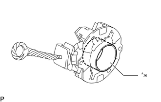
When installing a new part:
- NOTICE:
-
Do not remove the retainer.
| *a | Retainer |
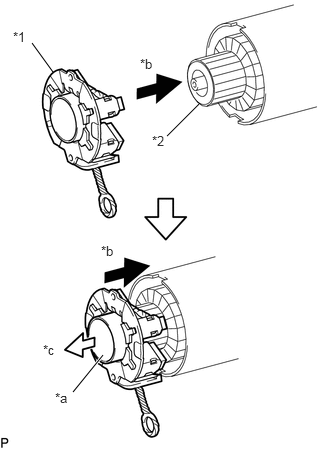
With the retainer installed, push the starter brush holder assembly onto the starter armature assembly.
| *1 | Starter Brush Holder Assembly |
| *2 | Starter Armature Assembly |
| *a | Retainer |
| *b | Push Starter Brush Holder Assembly in this Direction |
| *c | Push out Retainer in this Direction |
- NOTICE:
-
Be careful not to damage the brushes when pushing the starter brush holder assembly in place.
- HINT:
-
Install the starter brush holder assembly as shown in the illustration, as the installation direction is fixed.
Push the starter brush holder assembly onto the starter armature assembly while pushing out the retainer with the end of the starter armature assembly.
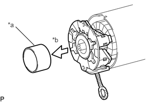
Push the starter brush holder assembly onto the starter armature assembly until the retainer is completely pushed out.
| *a | Retainer |
| *b | Push out Retainer in this Direction |
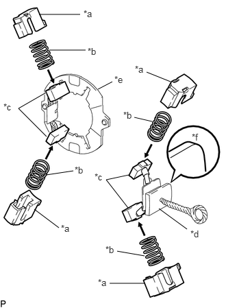
When reinstalling:
Set the spring inside the holder box. Then, push the brush inside the holder box in the orientation shown in the illustration.
- NOTICE:
-
Install the holder boxes so the rounded corner of the rubber portion of the lead wire faces the holder plate.
- HINT:
-
Install the holder boxes with their claws facing the holder plate.
| *a | Holder Box |
| *b | Spring |
| *c | Brush |
| *d | Rubber Part |
| *e | Holder Plate |
| *f | Rounded Corner of Lead Wire Rubber Part |
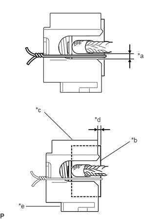
With the brush pushed inside, use wire or similar material to fix the brush in the position shown in the illustration.
| *a | Range for Wire Used to Fix Brush |
| *b | Brush |
| *c | Holder Box |
| *d | 1 mm or less |
| *e | Claw of the Holder Box |
- NOTICE:
- ·
When fixing the brush in place using wire or similar material, be careful not to damage the brush.
·Fix the brush in place so that it protrudes from the holder box by 1 mm or less.
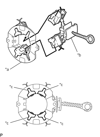
Insert the claw of the holder box into the holder plate to fix the holder box in place.
| *a | Holder Plate |
| *b | Rounded Corner of Lead Wire Rubber Part |
| *c | Claw of the Holder Box |
- NOTICE:
- ·
Install the holder boxes so the rounded corner of the rubber portion of the lead wire faces the holder plate.
·Check that the 4 claws of the holder boxes are fixed to the holder plate.
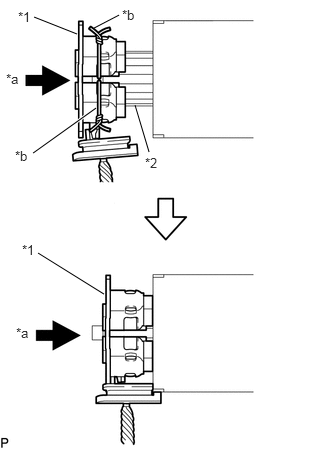
Push the starter brush holder assembly onto the starter armature assembly, but leave enough room to remove the wire or similar material.
| *1 | Starter Brush Holder Assembly |
| *2 | Starter Armature Assembly |
| *a | Push Starter Brush Holder Assembly in this Direction |
| *b | Assembly in this Direction Wire |
Remove the 4 pieces of wire or similar material and then push the starter brush holder assembly all the way onto the starter armature assembly.
- NOTICE:
-
When removing the wire or similar material, be careful not to damage the brush.
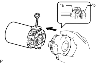
Align the rubber part of the starter yoke assembly with the groove of the starter commutator end frame assembly.
| *a | Rubber Part |
| *b | Starter Commutator End Frame Assembly |
Install the starter commutator end frame assembly with the 2 screws.
- Torque:
- 1.5 N*m (15 kgf*cm, 13 in.*lbf)
28120
3.INSTALL STARTER YOKE ASSEMBLY
Install the rubber seal to the repair service starter kit.
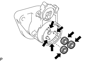
Apply high-temperature grease to the planetary gears and pins of the repair service starter kit as shown in the illustration.

|
High-temperature Grease |
Install the 3 planetary gears to the repair service starter kit.
Install the starter armature plate to the starter yoke assembly.
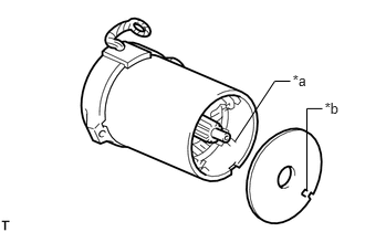
Check that the notch of the starter armature plate fits over the protrusion of the starter yoke assembly.
| *a | Protrusion |
| *b | Notch |
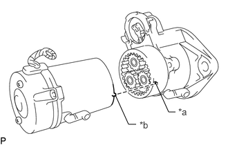
Align the protrusion of the starter yoke assembly with the notches inside the repair service starter kit and insert the starter yoke assembly into the repair service starter kit.
| *a | Notches |
| *b | Protrusion |
Using a T25 "TORX" socket wrench, install the repair service starter kit with the 2 bolts.
- Torque:
- 6.0 N*m (61 kgf*cm, 53 in.*lbf)
28150
4.INSTALL MAGNET STARTER SWITCH ASSEMBLY
Apply high-temperature grease to the plunger hook of the magnet starter switch assembly.
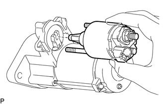
Hang the plunger hook of the magnet starter switch assembly on the starter pinion drive lever from the upper side.
Install the magnet starter switch assembly with the 2 nuts.
- Torque:
- 7.5 N*m (76 kgf*cm, 66 in.*lbf)
Connect the lead wire to terminal C with the nut.
- Torque:
- 10 N*m (102 kgf*cm, 7 ft.*lbf)