RA61F MANUAL TRANSMISSION / TRANSAXLE COUNTER GEAR REASSEMBLY
PROCEDURE

 33421G
1.INSTALL COUNTER GEAR REAR RADIAL BALL BEARING
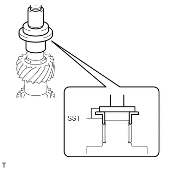
Using SST and a press, install a new radial ball bearing (inner race) to the counter gear.
- SST
- 09316-60011 (09316-00041)
09950-60010 (09951-00540)
33411R
2.INSTALL COUNTER GEAR REAR BEARING SNAP RING
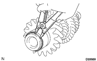
Select a new snap ring that will allow minimal axial play.
- Standard clearance:
0.1 mm (0.00394 in.) or less
- Standard Snap Ring:
Part No. Mark Thickness 90520-31015 A 2.35 to 2.40 mm
(0.0925 to 0.0945 in.)90520-31016 B 2.40 to 2.45 mm
(0.0945 to 0.0965 in.)90520-31017 C 2.45 to 2.50 mm
(0.0965 to 0.0984 in.)90520-31018 D 2.50 to 2.55 mm
(0.0984 to 0.1004 in.)90520-31019 E 2.55 to 2.60 mm
(0.1004 to 0.1024 in.)90520-31020 F 2.60 to 2.65 mm
(0.1024 to 0.1043 in.)90520-31021 G 2.65 to 2.70 mm
(0.1043 to 0.1063 in.)90520-31022 H 2.70 to 2.75 mm
(0.1063 to 0.1083 in.)90520-31023 J 2.75 to 2.80 mm
(0.1083 to 0.1102 in.)90520-31024 K 2.80 to 2.85 mm
(0.1102 to 0.1122 in.)90520-31025 L 2.85 to 2.90 mm
(0.1122 to 0.1142 in.)90520-31033 M 2.90 to 2.95 mm
(0.1142 to 0.1161 in.)
Using a snap ring expander, install the snap ring to the counter gear.
33361
3.INSTALL NO. 1 TRANSMISSION CLUTCH HUB
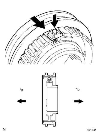
Apply a light coat of gear oil to the sleeve and hub.
Install the clutch hub to the clutch hub sleeve.
| *a | 1st Gear Side |
| *b | 2nd Gear Side |
Install one of the balls to each shifting key.
Install one of the springs to each shifting key.
Install the shifting keys with balls and springs to the No. 1 clutch hub.
- NOTICE:
-
Be careful to prevent the balls from flying off.
33332B
4.INSTALL 2ND GEAR NEEDLE ROLLER BEARING
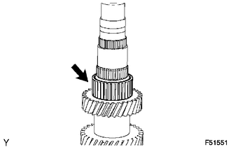
Coat the 2nd gear needle roller bearing with gear oil, and then install it to the counter gear.
33424
5.INSTALL COUNTER SHAFT 2ND SPEED GEAR
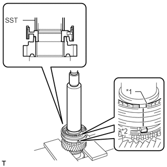
Coat the counter shaft 2nd speed gear with gear oil, and then install it to the counter gear.
Coat the No. 1 synchronizer ring set with gear oil, and then install it to the counter gear.
Using SST and a press, install the No. 1 transmission clutch hub to the counter gear.
- SST
- 09316-60011
| *a | Groove |
| *b | Protrusion |
- HINT:
-
Align the groove of the clutch hub with the protrusion of the synchronizer ring.
Check that the gear and synchronizer ring move smoothly.
33361B
6.INSTALL NO. 1 CLUTCH HUB SHAFT SNAP RING
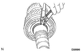
Select a new snap ring that will allow minimal axial play.
- Standard clearance:
0.1 mm (0.00394 in.) or less
- Standard Snap Ring:
Part No. Mark Thickness 90520-45013 A 2.28 to 2.33 mm
(0.0898 to 0.0917 in.)90520-45014 B 2.33 to 2.38 mm
(0.0917 to 0.0937 in.)90520-45015 C 2.38 to 2.43 mm
(0.0937 to 0.0957 in.)90520-45016 D 2.43 to 2.48 mm
(0.0957 to 0.0976 in.)90520-45017 E 2.48 to 2.53 mm
(0.0976 to 0.0996 in.)90520-45018 F 2.53 to 2.58 mm
(0.0996 to 0.1016 in.)90520-45019 G 2.58 to 2.63 mm
(0.1016 to 0.1035 in.)
Using a snap ring expander, install the snap ring to the counter gear.
33037B
7.INSTALL NO. 1 SYNCHRONIZER RING SET (for 1st Gear)
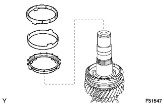
Coat the No. 1 synchronizer ring set with gear oil, and then install it to the counter gear.
33335C
8.INSTALL 1ST GEAR NEEDLE ROLLER BEARING
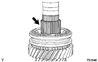
Coat the 1st gear needle roller bearing with gear oil, and then install it to the counter gear.
33426A
9.INSTALL COUNTER SHAFT 1ST SPEED GEAR
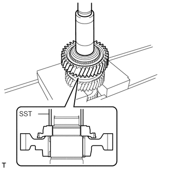
Coat the counter shaft 1st speed gear with gear oil and install it to the counter gear.
Using SST and a press, install the reverse gear spline piece.
- SST
- 09309-37010
33365C
10.INSTALL BALL
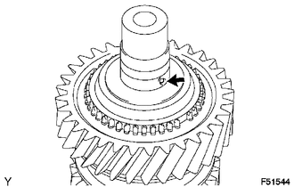
Install the ball to the counter gear.
33369B
11.INSTALL NO. 4 SYNCHRONIZER RING
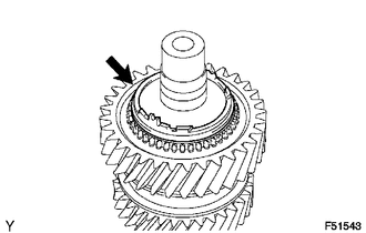
Coat the No. 4 synchronizer ring with gear oil and install it to the counter gear.
12.INSTALL REVERSE GEAR NEEDLE ROLLER BEARING
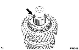
Coat the reverse gear needle roller bearing with gear oil and install it to the counter gear.
33425
13.INSTALL COUNTERSHAFT REVERSE GEAR
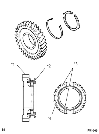
Install the key spring and 2 shifting keys to the reverse gear.
| *1 | Reverse Gear |
| *2 | Hub Sleeve |
| *3 | Shifting Key |
| *4 | Key Spring |
- HINT:
- ·
Install each shifting key with its groove on the reverse gear side.
·Install the key spring with its claw on the reverse gear side.
·Refer to the illustration when installing the key spring.
Install the hub sleeve to the reverse gear.
Coat the countershaft reverse gear with gear oil, and then install it to the counter gear.
33354A
14.INSTALL REVERSE GEAR BEARING RACE INNER
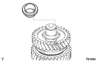
Align the groove of the reverse gear bearing race inner with the ball and install the reverse gear bearing race inner.
33411A
15.INSTALL COUNTER GEAR FRONT BEARING
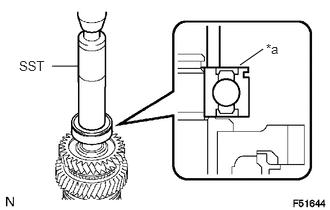
Using SST and a press, install the counter gear front bearing or roller to the counter gear.
- SST
- 09608-06041
| *a | Groove |
- HINT:
-
Make sure that the groove of the bearing faces the correct direction as shown in the illustration.
33411D
16.INSTALL NO. 1 COUNTER GEAR FRONT BEARING SNAP RING
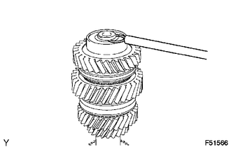
Select a new snap ring that will allow minimal axial play.
- Standard clearance:
0.1 mm (0.00394 in.) or less
- Standard Snap Ring:
Part No. Mark Thickness 90520-31015 A 2.35 to 2.40 mm
(0.0925 to 0.0945 in.)90520-31016 B 2.40 to 2.45 mm
(0.0945 to 0.0965 in.)90520-31017 C 2.45 to 2.50 mm
(0.0965 to 0.0984 in.)90520-31018 D 2.50 to 2.55 mm
(0.0984 to 0.1004 in.)90520-31019 E 2.55 to 2.60 mm
(0.1004 to 0.1024 in.)90520-31020 F 2.60 to 2.65 mm
(0.1024 to 0.1043 in.)90520-31021 G 2.65 to 2.70 mm
(0.1043 to 0.1063 in.)90520-31022 H 2.70 to 2.75 mm
(0.1063 to 0.1083 in.)90520-31023 J 2.75 to 2.80 mm
(0.1083 to 0.1102 in.)90520-31024 K 2.80 to 2.85 mm
(0.1102 to 0.1122 in.)90520-31025 L 2.85 to 2.90 mm
(0.1122 to 0.1142 in.)0520-31033 M 2.90 to 2.95 mm
(0.1142 to 0.1161 in.)
Using a snap ring expander, install the snap ring to the counter gear.
33425
17.INSPECT REVERSE GEAR THRUST CLEARANCE
33426A
18.INSPECT 1ST GEAR THRUST CLEARANCE
33424
19.INSPECT 2ND GEAR THRUST CLEARANCE
33425
20.INSPECT REVERSE GEAR RADIAL CLEARANCE
33426A
21.INSPECT 1ST GEAR RADIAL CLEARANCE
33424
22.INSPECT 2ND GEAR RADIAL CLEARANCE