RM27T0E
_52
Drivetrain
_053705
AXLE AND DIFFERENTIAL
_0260859
DIFFERENTIAL SYSTEM
U
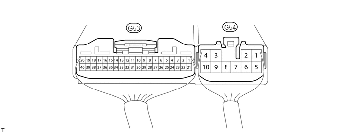
AXLE AND DIFFERENTIAL DIFFERENTIAL SYSTEM TERMINALS OF ECU
CHECK 4WD CONTROL ECU
2.688,0.51 2.99,0.677
0.302,0.167
10
false
G53
4.708,0.49 5.01,0.656
0.302,0.167
10
false
G54
a.
Measure the voltage and resistance according to the value(s) in the table below.
| Terminal No. (Symbol) | Wiring Color | Terminal Description | Condition | Specified Condition |
|---|---|---|---|---|
| G53-9 (RLY1) - G54-4 (GND) | G - W-B | Rear differential lock actuator limit switch | Ignition switch ON
Rear differential lock actuator limit switch on |
Below 1.5 V |
| Ignition switch ON
Rear differential lock actuator limit switch off |
11 to 14 V | |||
| G53-10 (RLY2) - G54-4 (GND) | P - W-B | Rear differential lock actuator limit switch | Ignition switch ON
Rear differential lock actuator limit switch on |
Below 1.5 V |
| Ignition switch ON
Rear differential lock actuator limit switch off |
11 to 14 V | |||
| G53-3 (R) - G54-4 (GND) | R - W-B | w/ Combination Switch:
Center cluster module switch (Rear differential lock control switch) |
Ignition switch ON
Rear differential lock switch on |
Below 1.5 V |
| Ignition switch ON
Rear differential lock switch off |
11 to 14 V | |||
| w/o Combination Switch:
Differential lock switch |
Ignition switch ON
Rear differential lock switch on |
Below 1.5 V | ||
| Ignition switch ON
Rear differential lock switch off |
11 to 14 V | |||
| G53-15 (RLP) - G54-4 (GND) | V - W-B | Rear differential lock detection switch | Ignition switch ON
Rear differential lock detection switch on |
Below 1.5 V |
| Ignition switch ON
Rear differential lock detection switch off |
9.5 to 14 V | |||
| G54-1 (M1) - G54-4 (GND) | B - W-B | Differential lock actuator motor | Ignition switch ON
Differential lock switch off → on (Differential lock switch OFF → ON (For 5 seconds after power supplied or until switching of limit switch is complete during FREE to LOCK switching)) |
11 to 14 V |
| Ignition switch ON
Differential lock switch off → on (Differential lock actuator motor stopped) |
Below 1.5 V | |||
| G54-3 (IG) - G54-4 (GND) | R - W-B | IG power | Ignition switch ON | 11 to 14 V |
| G54-4 (GND) - Body ground | W-B - Body ground | Ground | Always | Below 1 Ω |
| G54-5 (M2) - G54-4 (GND) | Y - W-B | Differential lock actuator motor | Ignition switch ON
Differential lock switch on → off (Differential lock switch ON → OFF (For 5 seconds after power supplied or until switching of limit switch is complete during LOCK to FREE switching)) |
11 to 14 V |
| Ignition switch ON
Differential lock switch on → off (Differential lock actuator motor stopped) |
Below 1.5 V | |||
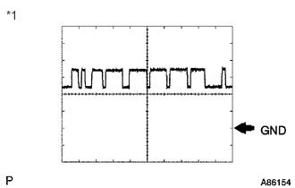
| G53-19 (CANH) - G54-4 (GND) | G - W-B | CAN communication line | Ignition switch ON | Pulse generation (see waveform 1) |
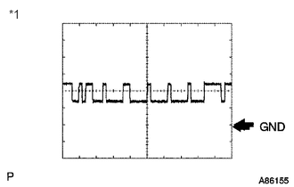
| G53-20 (CANL) - G54-4 (GND) | W - W-B | CAN communication line | Ignition switch ON | Pulse generation (see waveform 2) |
b.
0.073,0.094 0.302,0.302
0.229,0.208
10
false
*1
Using an oscilloscope, check waveform 1.
| Item | Content |
|---|---|
| Terminal No. (Symbol) | F47-19 (CANH) - F46-4 (GND) |
| Tool setting | 1 V/DIV., 10 μsec./DIV. |
| Condition | Engine stopped and ignition switch ON |
| *1 | Waveform 1 |
- HINT:
-
The waveform varies depending on the CAN communication signal.
c.
0.104,0.083 0.771,0.281
0.667,0.198
10
false
*1
Using an oscilloscope, check waveform 2.
| Item | Content |
|---|---|
| Terminal No. (Symbol) | F47-20 (CANL) - F46-4 (GND) |
| Tool setting | 1 V/DIV., 10 μsec./DIV. |
| Condition | Engine stopped and ignition switch ON |
| *1 | Waveform 2 |
- HINT:
-
The waveform varies depending on the CAN communication signal.