REAR SUSPENSION REAR PNEUMATIC CYLINDER(w/ Air Suspension) INSTALLATION
CAUTION / NOTICE / HINT
- HINT:
- ·
Use the same procedure for the RH and LH sides.
·The procedure listed below is for the LH side.
·A bolt without a torque specification is shown in the standard bolt chart (See page General>SPECIFICATIONS>STANDARD BOLT>SPECIFIED TORQUE FOR STANDARD BOLTS).
PROCEDURE

 48090B
1.INSTALL REAR PNEUMATIC CYLINDER ASSEMBLY LH
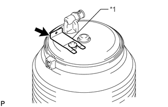
Install the pneumatic cylinder assembly with the clip.
| *1 | Clip |
- NOTICE:
-
Make sure that the clip is installed securely to the cylinder.
Connect the height control tube (See page Suspension>SUSPENSION CONTROL>SUSPENSION CONTROL SYSTEM (w/ Air Suspension)>PRECAUTION).
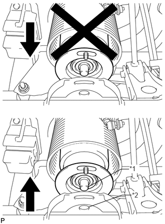
When using safety stands and a jack:
Jack up the rear axle assembly until the bottom of the pneumatic cylinder assembly touches the rear axle assembly and install the pin at the lower side of the pneumatic cylinder assembly to the hole in the rear axle housing.
| *1 | Pin |
| *2 | Hole |
- NOTICE:
- ·
Do not extend the pneumatic cylinder assembly for pin installation.
·Make sure that the pin at the lower side of the pneumatic cylinder assembly fits in the hole in the rear axle housing.
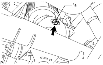
Temporarily install the nut.
Align the matchmarks on the rear pneumatic cylinder with the matchmarks on the rear axle housing.
| *a | Matchmark |
Remove the safety stands with care not to extend the pneumatic cylinder assembly when lowering the vehicle until it sits on the ground.
- NOTICE:
- ·
Do not extend the pneumatic cylinder assembly by lowering the rear axle assembly with safety stands installed.
·Make sure that the diaphragm of the pneumatic cylinder assembly is not deformed.
When using a swing arm type lift:
Lower the vehicle until the tires contact the ground, and continue lowering the vehicle slowly until the bottom of the pneumatic cylinder assembly touches the rear axle housing.
Align the seating pin on the cylinder with the hole in the rear axle assembly and install the pneumatic cylinder assembly to the rear axle housing.
- NOTICE:
- ·
Do not extend the pneumatic cylinder assembly for pin installation.
·Make sure that the pin at the lower side of the pneumatic cylinder assembly fits in the hole in the rear axle housing.
Temporarily install the nut.
Align the matchmarks on the rear pneumatic cylinder with the matchmarks on the rear axle housing.
| *a | Matchmark |
Lower the lift carefully so as not to extend the pneumatic cylinder assembly.
- NOTICE:
- ·
Do not extend the pneumatic cylinder assembly by lifting down the rear axle housing after installing the pin.
·Make sure that the diaphragm of the pneumatic cylinder assembly is not deformed.
Start the engine and replenish the pneumatic cylinder assembly with air.
Tighten the nut.
- Torque:
- 20 N*m (204 kgf*cm, 15 ft.*lbf)
2.INSPECT FOR AIR LEAK
Inspect for air leaks (See page Suspension>SUSPENSION CONTROL>SUSPENSION CONTROL SYSTEM (w/ Air Suspension)>PRECAUTION).
3.INSPECT VEHICLE HEIGHT
Inspect the vehicle height (See page Suspension>SUSPENSION CONTROL>SUSPENSION CONTROL SYSTEM (w/ Air Suspension)>ON-VEHICLE INSPECTION).