Home › Steering › STEERING COLUMN › STEERING WHEEL › 2015.06–2017.08
RM27T0E _55 Steering _053718 STEERING COLUMN _0260959 STEERING WHEEL G

STEERING COLUMN  STEERING WHEEL  INSPECTION  


PROCEDURE

Hide 84250A 1.INSPECT STEERING PAD SWITCH ASSEMBLY (w/ Audio + Monitor + Tel + Voice + Multi Function + Distance Control)

a.

Inspect the pad switch.

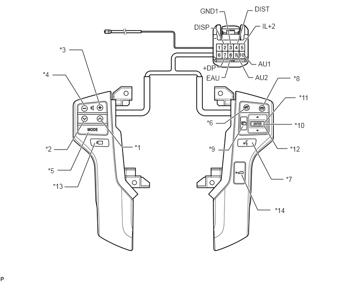
C215869E02
1.75,2.188 1.354,1.552 1.354,1.552 1.083,1.552 true 2.063,2.177 1.698,1.031 1.698,1.031 1.427,1.031 true 1.74,2.49 1.385,3.094 1.385,3.094 1.115,3.094 true 1.823,2.74 1.458,3.521 1.458,3.521 1.188,3.521 true 1.958,2.958 1.604,3.865 1.604,3.865 1.333,3.865 true 2.083,2.479 2.521,3.042 2.521,3.042 2.74,3.042 true 5.438,2.177 5.74,1.615 5.74,1.615 6,1.615 true 5.052,2.25 4.635,2.552 4.635,2.552 4.458,2.552 true 5.438,2.573 5.729,3.073 5.729,3.073 5.938,3.073 true 5.208,2.948 5.604,3.708 5.604,3.708 5.854,3.708 true 4.99,3.615 5.323,4.344 5.323,4.344 5.583,4.344 true 5.01,2.615 4.719,3.104 4.719,3.104 4.51,3.104 true 5.438,2.563 5.896,2.021 5.896,2.021 6.104,2.021 true 5.438,2.573 6.031,2.573 true 5.021,0.917 5.281,0.542 5.281,0.542 5.375,0.542 true 4.771,0.938 4.635,0.24 4.635,0.24 4.531,0.24 true 4.635,0.927 4.458,0.583 4.458,0.583 4.354,0.583 true 5.052,1.146 5.198,1.333 5.198,1.333 5.292,1.333 true 4.896,1.146 5.135,1.604 5.135,1.604 5.229,1.604 true 4.656,1.177 4.552,1.385 4.552,1.385 4.479,1.385 true 4.771,1.167 4.646,1.604 4.646,1.604 4.573,1.604 true 4.896,0.927 5.115,0.219 5.115,0.219 5.219,0.219 true 2.781,2.969 3.031,3.188 0.25,0.219 10 false *1 0.885,1.458 1.208,1.698 0.323,0.24 10 false *4 0.938,3 1.188,3.229 0.25,0.229 10 false *2 1.229,0.948 1.552,1.188 0.323,0.24 10 false *3 0.99,3.448 1.313,3.688 0.323,0.24 10 false *5 5.906,3.625 6.229,3.865 0.323,0.24 10 false *7 4.271,2.458 4.594,2.698 0.323,0.24 10 false *6 6.063,1.542 6.385,1.781 0.323,0.24 10 false *8 4.313,3 4.635,3.24 0.323,0.24 10 false *9 6.083,2.51 6.406,2.75 0.323,0.24 10 false *10 6.177,1.938 6.5,2.177 0.323,0.24 10 false *11 5.99,3 6.313,3.24 0.323,0.24 10 false *12 1.094,3.771 1.417,4.01 0.323,0.24 10 false *13 5.677,4.271 6,4.51 0.323,0.24 10 false *14 4.01,0.479 4.448,0.656 0.438,0.177 10 false DISP 4.135,0.146 4.573,0.323 0.438,0.177 10 false GND1 5.417,0.458 5.854,0.635 0.438,0.177 10 false IL+2 4.188,1.323 4.625,1.5 0.438,0.177 10 false +DP 4.26,1.531 4.698,1.708 0.438,0.177 10 false EAU 5.333,1.24 5.771,1.417 0.438,0.177 10 false AU1 5.271,1.521 5.708,1.708 0.438,0.188 10 false AU2 5.26,0.104 5.698,0.281 0.438,0.177 10 false DIST

Text in Illustration
*1 Seek+ Switch *2 Seek- Switch
*3 Volume+ Switch *4 Volume- Switch
*5 MODE Switch *6 Off Hook Switch
*7 w/ Voice Switch *8 On Hook Switch
*9 Menu Switch *10 ENTER Switch
*11 UP/DOWN Up Switch *12 UP/DOWN Down Switch
*13 w/ Wide View Front and Side Monitor Switch *14 w/ Distance Control Switch

i.

Measure the resistance according to the value(s) in the table below.

Standard Resistance:
Tester Connection Condition Specified Condition
10 (AU1) - 8 (EAU) No switch pushed 95 to 105 kΩ
Seek+ switch pushed Below 2.5 Ω
Seek- switch pushed 313 to 345 Ω
Volume+ switch pushed 950 to 1050 Ω
Volume- switch pushed 2950 to 3265 Ω
9 (AU2) - 8 (EAU) No switch pushed 95 to 105 kΩ
MODE switch pushed Below 2.5 Ω
On hook switch pushed 313 to 345 Ω
Off hook switch pushed 950 to 1050 Ω
Voice switch pushed *7 2950 to 3265 Ω
2 (DISP) - 3 (GND1) No switch pushed 95 to 105 kΩ
Menu switch pushed Below 2.5 Ω
ENTER switch pushed 313 to 345 Ω
UP/DOWN Up switch pushed 2950 to 3265 Ω
UP/DOWN Down switch pushed 950 to 1050 Ω
7 (+DP) - 3 (GND1) Wide View Front and Side Monitor switch pushed *13 Below 2.5 Ω
4 (DIST) - 6 (ECC) Distance Control switch pushed *14 Below 2.5 Ω


If the result is not as specified, replace the steering pad switch assembly.


b.

Check the illumination.

i.

Connect the battery positive (+) lead to terminals IL+2 and the negative (-) lead to terminals EAU and GND1 of the steering pad switch assembly connector.


ii.

Check that the switch illumination comes on.

OK:

Steering pad switch illumination comes on.


If the result is not as specified, replace the steering pad switch assembly.


Hide 84250A 2.INSPECT STEERING PAD SWITCH ASSEMBLY (w/ Audio + Tel)

a.

Inspect the pad switch.

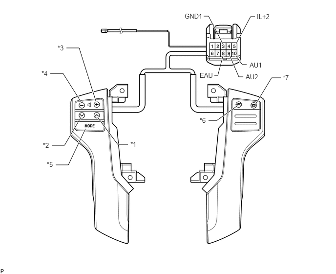
C294210E02
1.74,2.188 1.344,1.563 1.344,1.563 1.073,1.563 true 2.052,2.177 1.688,1.021 1.688,1.021 1.417,1.021 true 1.729,2.49 1.375,3.094 1.375,3.094 1.104,3.094 true 1.823,2.74 1.458,3.51 1.458,3.51 1.188,3.51 true 2.083,2.5 2.51,3.073 2.51,3.073 2.729,3.073 true 5.458,2.208 5.792,1.656 5.792,1.656 5.99,1.656 true 5.063,2.25 4.625,2.563 4.625,2.563 4.448,2.563 true 5.031,0.938 5.344,0.354 5.344,0.354 5.438,0.354 true 5.031,1.188 5.167,1.375 5.167,1.375 5.26,1.375 true 4.896,1.177 5.094,1.635 5.094,1.635 5.188,1.635 true 4.76,1.167 4.646,1.604 4.646,1.604 4.573,1.604 true 4.75,0.927 4.448,0.344 4.448,0.344 4.344,0.344 true 2.781,2.99 3.031,3.208 0.25,0.219 10 false *1 1.229,0.938 1.552,1.177 0.323,0.24 10 false *3 0.917,3.01 1.167,3.24 0.25,0.229 10 false *2 0.885,1.479 1.208,1.719 0.323,0.24 10 false *4 1,3.417 1.323,3.656 0.323,0.24 10 false *5 4.26,2.479 4.583,2.719 0.323,0.24 10 false *6 6.031,1.573 6.354,1.813 0.323,0.24 10 false *7 5.479,0.271 5.917,0.448 0.438,0.177 10 false IL+2 4.26,1.521 4.698,1.698 0.438,0.177 10 false EAU 5.323,1.302 5.76,1.479 0.438,0.177 10 false AU1 5.24,1.552 5.677,1.729 0.438,0.177 10 false AU2 3.938,0.26 4.375,0.438 0.438,0.177 10 false GND1

Text in Illustration
*1 Seek+ Switch *2 Seek- Switch
*3 Volume+ Switch *4 Volume- Switch
*5 MODE Switch *6 Off Hook Switch
*7 On Hook Switch - -

i.

Measure the resistance according to the value(s) in the table below.

Standard Resistance:
Tester Connection Condition Specified Condition
10 (AU1) - 8 (EAU) No switch pushed 95 to 105 kΩ
Seek+ switch pushed Below 2.5 Ω
Seek- switch pushed 313 to 345 Ω
Volume+ switch pushed 950 to 1050 Ω
Volume- switch pushed 2950 to 3265 Ω
9 (AU2) - 8 (EAU) No switch pushed 95 to 105 kΩ
MODE switch pushed Below 2.5 Ω
On hook switch pushed 313 to 345 Ω
Off hook switch pushed 950 to 1050 Ω


If the result is not as specified, replace the steering pad switch assembly.


b.

Check the illumination.

i.

Connect the battery positive (+) lead to terminals IL+2 and the negative (-) lead to terminals EAU and GND1 of the steering pad switch assembly connector.


ii.

Check that the switch illumination comes on.

OK:

Steering pad switch illumination comes on.


If the result is not as specified, replace the steering pad switch assembly.


Hide 84244B 3.INSPECT STEERING PAD SWITCH RH

a.

Inspect the pad switch.

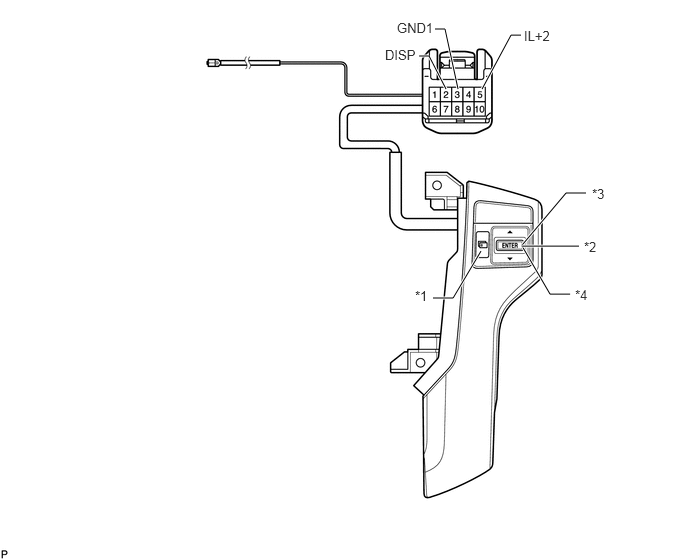
C216960E02
5.438,2.563 5.729,3.063 5.729,3.063 5.938,3.063 true 5.01,2.615 4.719,3.104 4.719,3.104 4.51,3.104 true 5.438,2.552 5.896,2.01 5.896,2.01 6.104,2.01 true 5.438,2.563 6.031,2.563 true 5.021,0.927 5.323,0.365 5.323,0.365 5.427,0.365 true 4.771,0.927 4.635,0.302 4.635,0.302 4.531,0.302 true 4.646,0.927 4.469,0.583 4.469,0.583 4.365,0.583 true 4.323,3 4.646,3.24 0.323,0.24 10 false *1 6.083,2.49 6.406,2.729 0.323,0.24 10 false *2 6.167,1.938 6.49,2.177 0.323,0.24 10 false *3 5.99,2.99 6.313,3.229 0.323,0.24 10 false *4 4.01,0.49 4.448,0.667 0.438,0.177 10 false DISP 4.135,0.208 4.573,0.385 0.438,0.177 10 false GND1 5.458,0.292 5.896,0.469 0.438,0.177 10 false IL+2

Text in Illustration
*1 Menu Switch *2 ENTER Switch
*3 UP/DOWN Up Switch *4 UP/DOWN Down Switch

i.

Measure the resistance according to the value(s) in the table below.

Standard Resistance:
Tester Connection Condition Specified Condition
2 (DISP) - 3 (GND1) No switch pushed 95 to 105 kΩ
Menu switch pushed Below 2.5 Ω
ENTER switch pushed 313 to 345 Ω
UP/DOWN Up switch pushed 2950 to 3265 Ω
UP/DOWN Down switch pushed 950 to 1050 Ω


If the result is not as specified, replace the steering pad switch RH.


b.

Check the illumination.

i.

Connect the battery positive (+) lead to terminals IL+2 and the negative (-) lead to terminals GND1 of the steering pad RH connector.


ii.

Check that the switch illumination comes on.

OK:

Steering pad switch illumination comes on.


If the result is not as specified, replace the steering pad switch assembly.