AUDIO / VIDEO LUGGAGE SPEAKER(for 5 Door) INSPECTION
PROCEDURE

 86160T
1.INSPECT REAR HEADER SPEAKER ASSEMBLY
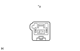
for Pioneer Made:
Measure the resistance according to the value(s) in the table below.
- Standard Resistance:
Tester Connection Condition Specified Condition 1 - 2 Always 4 Ω
If the result is not as specified, replace the rear header speaker assembly.
| *a | Component without harness connected
(Rear Header Speaker Assembly) |
for JBL Made:
When there is a malfunction such as noise from a speaker or no sound at all, replace the speaker with a new one and check that the malfunction disappears.
- OK:
Malfunction disappears.
- HINT:
- ·
Connect the connectors to the rear header speakers.
·When there is a possibility that either the right or left rear header speaker assembly is defective, inspect by interchanging the right one with the left one.
·Perform the inspection above on both the LH and RH sides.
86150
2.INSPECT NO. 1 SPEAKER ASSEMBLY WITH BOX
for Pioneer Made:
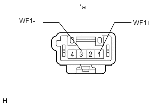
Measure the resistance according to the value(s) in the table below.
- Standard Resistance:
Tester Connection Condition Specified Condition 1 (WF1+) - 3 (WF1-) Always 2 Ω
If the result is not as specified, replace the No. 1 speaker assembly with box.
| *a | Component without harness connected
(No. 1 Speaker Assembly with Box) |
for JBL Made:
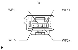
Measure the resistance according to the value(s) in the table below.
- Standard Resistance:
Tester Connection Condition Specified Condition 1 (WF1+) - 2 (WF2+) Always 1.6 to 2.4 Ω 3 (WF1-) - 4 (WF2-) Always 1.6 to 2.4 Ω
If the result is not as specified, replace the No. 1 speaker assembly with box.
| *a | Component without harness connected
(No. 1 Speaker Assembly with Box) |