RM27T0E
_56
Audio / Visual / Telematics
_053722
PARK ASSIST / MONITORING
_0260995
CLEARANCE SONAR MAIN SWITCH
G
PARK ASSIST / MONITORING CLEARANCE SONAR MAIN SWITCH INSPECTION
PROCEDURE

 84490A
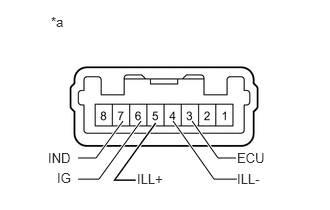
1.INSPECT BACK SONAR OR CLEARANCE SONAR SWITCH ASSEMBLY
2,1.26 2.271,1.646
2.271,1.646 2.458,1.646
true
1.802,1.26 2.229,1.865
2.229,1.865 2.469,1.865
true
1.469,1.26 1.031,1.865
1.031,1.865 0.813,1.865
true
1.281,1.26 1,1.646
1,1.646 0.813,1.646
true
2.469,1.563 2.823,1.708
0.354,0.146
10
false
ECU
2.469,1.781 2.76,1.927
0.292,0.146
10
false
ILL-
1.427,1.781 1.74,1.948
0.313,0.167
10
false
ILL+
0.5,1.563 0.771,1.729
0.271,0.167
10
false
IND
0.594,1.771 0.781,1.938
0.188,0.167
10
false
IG
0.531,0.146 0.708,0.313
0.177,0.167
10
false
*a
a.
Check the resistance.
i.
Measure the resistance according to the value(s) in the table below.
- Standard Resistance:
Tester Connection Switch Condition Specified Condition 3 (ECU) - 6 (IG) Sonar switch off 10 kΩ or higher Sonar switch on Below 1 Ω
If the result is not as specified, replace the back sonar or clearance sonar switch.
b.
Inspect the indicator operation.
- OK:
Measurement Condition Specified Condition Battery positive (+) → Terminal 3 (ECU)
Battery negative (-) → Terminal 7 (IND)LED illuminates
If the result is not as specified, replace the back sonar or clearance sonar switch.
c.
Inspect the illumination operation.
- OK:
Measurement Condition Specified Condition Battery positive (+) → Terminal 5 (ILL+)
Battery negative (-) → Terminal 4 (ILL-)LED illuminates
If the result is not as specified, replace the back sonar or clearance sonar switch.
| *a | Component without harness connected
(Back Sonar or Clearance Sonar Switch) |