RM27T0E
_56
Audio / Visual / Telematics
_053722
PARK ASSIST / MONITORING
_0261004
TOYOTA PARKING ASSIST-SENSOR SYSTEM(w/o Multi-display)
J
PARK ASSIST / MONITORING TOYOTA PARKING ASSIST-SENSOR SYSTEM(w/o Multi-display) Back-up Light Circuit
DESCRIPTION
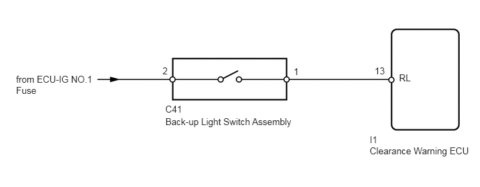
This circuit sends the back-up light switch signals to the clearance warning ECU.
WIRING DIAGRAM
5.521,2.177 7.104,2.656
1.583,0.479
10
false
Clearance Warning ECU
5.521,2.01 5.677,2.198
0.156,0.188
10
false
I1
2.469,1.74 4.458,1.917
1.99,0.177
10
false
Back-up Light Switch Assembly
2.469,1.552 3.844,1.74
1.375,0.188
10
false
C41
0.24,1.104 1.479,1.458
1.24,0.354
10
false
from ECU-IG NO.1 Fuse
5.958,1.083 6.198,1.271
0.24,0.188
10
false
RL
4.385,0.99 4.521,1.177
0.135,0.188
10
false
1
2.427,0.979 2.552,1.167
0.125,0.188
10
false
2
5.594,0.979 5.792,1.167
0.198,0.188
10
false
13
CAUTION / NOTICE / HINT
- NOTICE:
-
Inspect the fuses for circuits related to this system before performing the following inspection procedure.
PROCEDURE
1.INSPECT BACK-UP LIGHT SWITCH ASSEMBLY
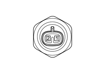
a.
Disconnect the C41 back-up light switch assembly connector.
b.
Measure the resistance according to the value(s) in the table below.
- Standard Resistance:
Tester Connection Switch Condition Specified Condition 1 - 2 Pushed Below 1 Ω 1 - 2 Released 10 kΩ or higher
| Result | Proceed to |
|---|---|
| OK | A |
| NG (for RA61F) | B |
| NG (for R150F) | C |
| NG (for G52F) | D |
A
2.CHECK HARNESS AND CONNECTOR (BACK-UP LIGHT SWITCH - BATTERY)
B
REPLACE BACK-UP LIGHT SWITCH ASSEMBLY
C
REPLACE BACK-UP LIGHT SWITCH ASSEMBLY
D
REPLACE BACK-UP LIGHT SWITCH ASSEMBLY
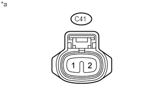
2.CHECK HARNESS AND CONNECTOR (BACK-UP LIGHT SWITCH - BATTERY)
a.
0.021,0 0.25,0.167
0.229,0.167
10
false
*a
1.563,0.313 1.854,0.469
0.292,0.156
10
false
C41
Disconnect the C41 back-up light switch assembly connector.
b.
Measure the voltage according to the value(s) in the table below.
- Standard Voltage:
Tester Connection Switch Condition Specified Condition C41-2 - Body ground Ignition switch ON 11 to 14 V C41-2 - Body ground Ignition switch off Below 1 V
| *a | Front view of wire harness connector
(to Back-up Light Switch Assembly) |
OK
3.CHECK HARNESS AND CONNECTOR (CLEARANCE WARNING ECU - BACK-UP LIGHT SWITCH)
NG
REPAIR OR REPLACE HARNESS OR CONNECTOR
3.CHECK HARNESS AND CONNECTOR (CLEARANCE WARNING ECU - BACK-UP LIGHT SWITCH)
a.
Disconnect the I1 clearance warning ECU connector.
b.
Disconnect the C41 back-up light switch assembly connector.
c.
Measure the resistance according to the value(s) in the table below.
- Standard Resistance:
Tester Connection Condition Specified Condition I1-13 (RL) - C41-1 (RL) Always Below 1 Ω I1-13 (RL) - Body ground Always 10 kΩ or higher
OK
PROCEED TO NEXT SUSPECTED AREA SHOWN IN PROBLEM SYMPTOMS TABLE
NG
REPAIR OR REPLACE HARNESS OR CONNECTOR