Home › Audio / Visual / Telematics › PARK ASSIST / MONITORING › TOYOTA PARKING ASSIST-SENSOR SYSTEM (w/o Multi-display) › 2015.06–2017.08
RM27T0E _56 Audio / Visual / Telematics _053722 PARK ASSIST / MONITORING _0261004 TOYOTA PARKING ASSIST-SENSOR SYSTEM(w/o Multi-display) D

PARK ASSIST / MONITORING  TOYOTA PARKING ASSIST-SENSOR SYSTEM(w/o Multi-display)  OPERATION CHECK  


CHECK INITIAL CHECK FUNCTION

a.
E107404E24
1.948,1.042 2.146,0.698 2.146,0.698 2.313,0.698 false 1.604,1.042 1.531,0.677 1.531,0.677 1.313,0.677 false 0.802,2.438 1.156,2.635 0.354,0.198 10 false Off 2.417,0.573 3.125,0.948 0.708,0.375 10 false 0.7 to 1.3 seconds 0.344,0.594 1.365,0.948 1.021,0.354 10 false Approximately 0.4 seconds 0.802,1.344 1.083,1.542 0.281,0.198 10 false On 0.104,0.052 1.24,0.271 1.135,0.219 10 false Buzzer Operation: 0.25,2.781 1.896,3.156 1.646,0.375 10 false Back Sonar or Clearance Sonar Switch On 2.5,2.615 3.188,3.177 0.688,0.563 10 false Detection Operation Starts

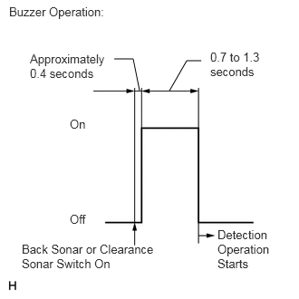
Check the initial check function for the buzzer.

i.

When the back sonar or clearance sonar switch is turned on, check that the following occurs: 1) after 0.4 seconds, the buzzer sounds for approximately 0.7 to 1.3 seconds, and 2) the system starts the obstacle detection operation.


b.

Check the initial check function for the sensor.

·

Approximately 0.4 seconds after the ignition switch is turned to ON and the back sonar or clearance sonar switch is turned on, all the sensors are checked by the system.

·

When the shift lever is operated, the system starts the obstacle detection operation.


c.

If a sensor is found to have an anomaly due to an open circuit, the buzzer sounds after the initial check function is completed to inform the driver and indicate which sensor is abnormal.

i.

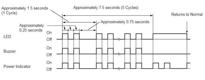
When the ECU determines that the sensor needs to be repaired or cleaned:
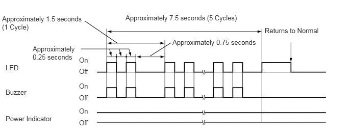
C159323E09
3.063,1.146 3.49,0.875 false 1.729,0.427 2.385,0.875 false 5.406,0.542 6.563,0.698 1.156,0.156 10 false Returns to Normal 1.615,1.146 2,1.313 0.385,0.167 10 false On 1.615,1.375 2,1.542 0.385,0.167 10 false Off 1.615,1.677 2,1.844 0.385,0.167 10 false On 1.615,1.917 2,2.083 0.385,0.167 10 false Off 1.615,2.188 2,2.354 0.385,0.167 10 false On 1.615,2.427 2,2.594 0.385,0.167 10 false Off 0.115,1.302 0.427,1.479 0.313,0.177 10 false LED 0.115,1.802 0.615,1.979 0.5,0.177 10 false Buzzer 0.115,2.344 1.146,2.521 1.031,0.177 10 false Power Indicator 0.042,0.302 1.76,0.667 1.719,0.365 10 false Approximately 1.5 seconds (1 Cycle) 2.563,0.281 4.969,0.469 2.406,0.188 10 false Approximately 7.5 seconds (5 Cycles) 3.521,0.781 5.313,0.969 1.792,0.188 10 false Approximately 0.75 seconds 0.667,0.917 1.625,1.26 0.958,0.344 10 false Approximately 0.25 seconds


ii.

When the ECU determines that the sensor needs to be cleaned:
C159324E08
3.073,1.042 3.49,0.771 false 1.76,0.344 2.396,0.76 false 5.99,0.417 7.146,0.573 1.156,0.156 10 false Returns to Normal 1.625,1.052 2.01,1.219 0.385,0.167 10 false On 1.625,1.292 2.01,1.458 0.385,0.167 10 false Off 1.625,1.594 2.01,1.76 0.385,0.167 10 false On 1.625,1.833 2.01,2 0.385,0.167 10 false Off 1.625,2.104 2.01,2.271 0.385,0.167 10 false On 1.625,2.344 2.01,2.51 0.385,0.167 10 false Off 0.125,1.198 0.438,1.375 0.313,0.177 10 false LED 0.125,1.708 0.625,1.885 0.5,0.177 10 false Buzzer 0.125,2.24 1.156,2.417 1.031,0.177 10 false Power Indicator 0.052,0.198 1.771,0.563 1.719,0.365 10 false Approximately 1.5 seconds (1 Cycle) 2.563,0.177 4.969,0.365 2.406,0.188 10 false Approximately 7.5 seconds (5 Cycles) 3.521,0.677 5.313,0.865 1.792,0.188 10 false Approximately 0.75 seconds 0.677,0.802 1.635,1.146 0.958,0.344 10 false Approximately 0.25 seconds

HINT:

If the clearance sonar switch is on and the ignition switch is turned to ON, the buzzer does not sound.


DETECTION RANGE MEASUREMENT AND INDICATOR CHECK


CAUTION:

Apply the parking brake securely so that the vehicle does not move.


a.

Turn the ignition switch to ON.


b.

Turn the back sonar or clearance sonar switch on.

c.

Move the shift lever to R to check the rear corner sensors and rear center sensors.


d.

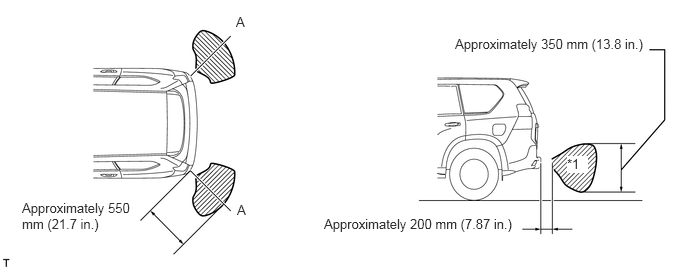
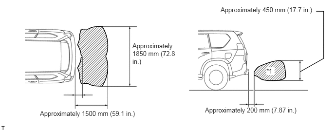
Move a pole around the sensor to measure the detection range of the sensor.

NOTICE:
·

These detection ranges are applicable when positioning a pole with a diameter of 60 mm (2.36 in.) parallel or perpendicular to the ground.

·

The ranges vary depending on the measuring method and type of obstacle (such as walls).

·

For close-range and medium-range detection, the values shown are for when using a pole with a diameter of 60 mm (2.36 in.). For long-range detection, the values shown are for when using walls.

·

The No. 1 ultrasonic sensor side view detection range hatched area*1 represents the cross section of the top view of the detection range along the lines labeled A. The hatched area*1 does not represent the entire side view detection range.


i.

Rear corner sensor detection range

U149266E04
0.229,2.083 1.375,2.427 1.146,0.344 10 false Approximately 550 mm (21.7 in.) 3.375,2.25 5.438,2.458 2.063,0.208 10 false Approximately 200 mm (7.87 in.) 2.469,2.104 2.646,2.313 0.177,0.208 10 false A 4.74,0.375 6.802,0.552 2.063,0.177 10 false Approximately 350 mm (13.8 in.) 5.906,1.625 6.125,1.802 0.219,0.177 10 true *1 2.458,0.146 2.615,0.323 0.156,0.177 10 false A


ii.

Rear center sensor detection range

U170605E03
0.854,2.344 3.115,2.531 2.26,0.188 10 false Approximately 1500 mm (59.1 in.) 2.833,0.896 3.771,1.406 0.938,0.51 10 false Approximately 1850 mm (72.8 in.) 4.385,2.271 6.479,2.479 2.094,0.208 10 false Approximately 200 mm (7.87 in.) 5.698,1.438 5.875,1.604 0.177,0.167 10 true *1 4.719,0.125 6.844,0.354 2.125,0.229 10 false Approximately 450 mm (17.7 in.)


e.

When the ultrasonic sensors have detected an obstacle, check that the buzzer sounds with the back sonar or clearance sonar switch on.

Operation Condition
Shift Lever Position Buzzer Operation
Back LH
Back RH
Rear Corner LH
Rear Corner RH
R Sounds Sounds

i.

Check that the buzzer sounds with the back sonar or clearance sonar switch on.

E132045E16
4.458,0.76 4.458,0.552 4.458,0.552 4.938,0.552 false 4.677,0.76 4.677,0.552 false 4.313,2.396 4.594,2.396 4.594,2.396 4.594,2.635 false 1.75,2.396 1.052,2.396 1.052,2.396 1.052,2.635 false 5.292,2.635 5.292,2.427 5.292,2.427 5.917,2.427 false 1.385,2.656 1.385,2.406 false 0.25,0.167 1.917,0.375 1.667,0.208 10 false 1. Close-range Detection 3.688,0.167 5.719,0.375 2.031,0.208 10 false 2. Medium-range Detection 3.698,1.823 6.385,2.031 2.688,0.208 10 false 4. Maximum Long-range Detection 0.24,1.833 2.031,2.042 1.792,0.208 10 false 3. Long-range Detection 3.781,0.906 4.083,1.052 0.302,0.146 10 false ON 3.771,1.323 4.135,1.469 0.365,0.146 10 false OFF 0.281,0.906 0.583,1.052 0.302,0.146 10 false ON 0.271,1.313 0.635,1.458 0.365,0.146 10 false OFF 3.813,2.771 4.115,2.917 0.302,0.146 10 false ON 3.802,3.167 4.167,3.313 0.365,0.146 10 false OFF 0.292,2.781 0.594,2.927 0.302,0.146 10 false ON 0.271,3.177 0.635,3.323 0.365,0.146 10 false OFF 3.313,2.313 4.375,2.469 1.063,0.156 10 false 150 +/-15 msec. 5.979,2.344 7.042,2.5 1.063,0.156 10 false 650 +/-65 msec. 1.823,2.323 2.885,2.479 1.063,0.156 10 false 150 +/-15 msec. 4.979,0.479 5.969,0.635 0.99,0.156 10 false 75 +/-7.5 msec.

Rear Corner Detection Range
Detection Distance
1. Close-range detection Within 250 +/-30 mm (9.84 +/-1.18 in.)
2. Medium-range detection 250 +/-30 to 375 +/-40 mm (9.84 +/-1.18 to 14.8 +/-1.57 in.)
3. Long-range detection 375 +/-40 to 550 +/-60 mm (14.8 +/-1.57 to 21.7 +/-2.36 in.)

Rear Center Detection Range
Detection Distance
1. Close-range detection Within 400 +/-40 mm (15.7 +/-1.57 in.)
2. Medium-range detection 400 +/-40 to 500 +/-50 mm (15.7 +/-1.57 to 19.7 +/-1.97 in.)
3. Long-range detection 500 +/-50 to 650 +/-70 mm (19.7 +/-1.97 to 25.6 +/-2.76 in.)
4. Maximum long-range detection 650 +/-70 to 1500 +/-150 mm (25.6 +/-2.76 to 59.1+/-5.91 in.)

HINT:

Ultrasonic waves are used to measure the detection range. However, the detection range may vary depending on the ambient temperature.


ii.

Check the indicator and buzzer when the rear center sensors and rear corner sensors have detected an obstacle.

Operation Condition
Ignition Switch Back Sonar or Clearance Sonar Switch Shift Lever Position
ON On R

Buzzer
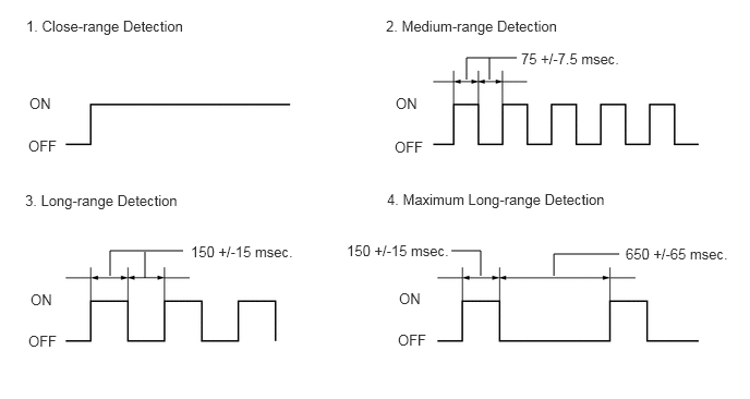
Detection Range Buzzer
1. Close-range detection Sounds continuously
2. Medium-range detection Sounds intermittently
(On: 75 msec./Off: 75 msec.)
3. Long-range detection Sounds intermittently
(On: 150 msec./Off: 150 msec.)
4. Maximum long-range detection Sounds intermittently
(On: 150 msec./Off: 650 msec.)

Clearance Warning Indicator
Detection Range Indicator Displayed
1. Close-range detection Corner indicator(s) are illuminated and/or back indicator is illuminated
2. Medium-range detection Corner indicator(s) are blinking and/or back indicator is blinking
3. Long-range detection Corner indicator(s) are blinking and/or back indicator is blinking
4. Maximum long-range detection Back indicator is blinking

E194315E03
3.063,1.323 2.802,1.469 false 4.115,1.313 4.385,1.458 false 3.708,1.49 3.979,1.646 false 0.083,0.031 1.344,0.281 1.26,0.25 10 false *1 2.646,1.406 2.802,1.583 0.156,0.177 10 false *a 4.406,1.406 4.563,1.583 0.156,0.177 10 false *a 4,1.573 4.156,1.781 0.156,0.208 10 false *b

Text in Illustration
*1 Clearance warning indicator - -
*a Corner indicator *b Back indicator

HINT:

Ultrasonic waves are used to measure the detection range. However, the detection range may vary depending on the ambient temperature.