Home › Power Source / Network › NETWORKING › CAN COMMUNICATION SYSTEM(for LHD with Entry and Start System) › 2015.06–2017.08
RM27T0E _57 Power Source / Network _053729 NETWORKING _0261031 CAN COMMUNICATION SYSTEM(for LHD with Entry and Start System) J

NETWORKING  CAN COMMUNICATION SYSTEM(for LHD with Entry and Start System)  ECM Communication Stop Mode  


DESCRIPTION

Detection Item Symptom Trouble Area
ECM Communication Stop Mode Either condition is met:
·

"ECM (Engine)" is not displayed on "Bus Check".

·

"ECM Communication Stop Mode" in "DTC Combination Table" applies.


·

Power source or inside ECM

·

ECM


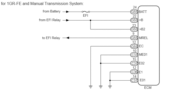
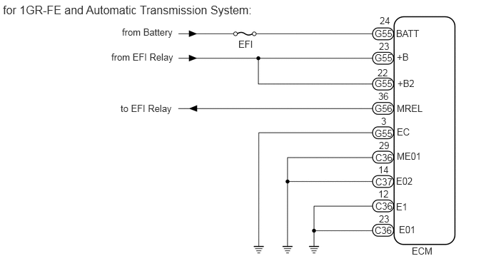
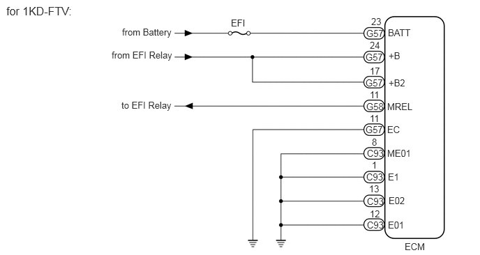
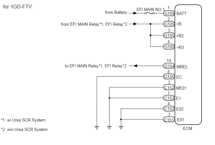
WIRING DIAGRAM

E346819E02
0.042,0.042 3.823,0.271 3.781,0.229 12 false for 1GR-FE and Manual Transmission System: 1.781,0.385 2.667,0.604 0.885,0.219 10 false from Battery 1.625,0.75 2.729,1.021 1.104,0.271 10 false from EFI Relay 1.76,1.5 2.865,1.771 1.104,0.271 10 false to EFI Relay 3.458,0.563 4.344,0.781 0.885,0.219 10 false EFI 5.469,0.406 5.854,0.594 0.385,0.188 10 false G55 5.542,0.219 5.927,0.406 0.385,0.188 10 false 24 5.781,0.406 6.167,0.594 0.385,0.188 10 false BATT 5.469,0.76 5.854,0.948 0.385,0.188 10 false G55 5.531,0.594 5.917,0.781 0.385,0.188 10 false 22 5.792,0.75 6.177,0.938 0.385,0.188 10 false +B 5.469,1.135 5.854,1.323 0.385,0.188 10 false G55 5.51,0.979 5.896,1.167 0.385,0.188 10 false 23 5.802,1.135 6.188,1.323 0.385,0.188 10 false +B2 5.469,1.5 5.854,1.688 0.385,0.188 10 false G55 5.521,1.323 5.906,1.51 0.385,0.188 10 false 9 5.792,1.5 6.177,1.688 0.385,0.188 10 false MREL 5.469,1.865 5.854,2.052 0.385,0.188 10 false G55 5.51,1.688 5.896,1.875 0.385,0.188 10 false 12 5.792,1.844 6.177,2.031 0.385,0.188 10 false EC 5.479,2.219 5.865,2.406 0.385,0.188 10 false C37 5.531,2.042 5.917,2.229 0.385,0.188 10 false 10 5.479,2.573 5.865,2.76 0.385,0.188 10 false C37 5.521,2.396 5.906,2.583 0.385,0.188 10 false 15 5.792,2.198 6.177,2.385 0.385,0.188 10 false ME01 5.781,2.563 6.167,2.75 0.385,0.188 10 false E02 5.479,2.927 5.865,3.115 0.385,0.188 10 false C36 5.521,2.75 5.906,2.938 0.385,0.188 10 false 12 5.781,2.938 6.167,3.125 0.385,0.188 10 false E1 5.469,3.281 5.854,3.469 0.385,0.188 10 false C37 5.531,3.115 5.917,3.302 0.385,0.188 10 false 14 5.823,3.271 6.208,3.458 0.385,0.188 10 false E01 6.01,3.583 6.396,3.771 0.385,0.188 10 false ECM

E346819E03
0.042,0.042 4.021,0.302 3.979,0.26 12 false for 1GR-FE and Automatic Transmission System: 1.781,0.385 2.667,0.604 0.885,0.219 10 false from Battery 1.625,0.75 2.729,1.021 1.104,0.271 10 false from EFI Relay 1.76,1.5 2.865,1.771 1.104,0.271 10 false to EFI Relay 3.479,0.563 4.365,0.781 0.885,0.219 10 false EFI 5.469,0.406 5.854,0.594 0.385,0.188 10 false G55 5.542,0.219 5.927,0.406 0.385,0.188 10 false 24 5.781,0.406 6.167,0.594 0.385,0.188 10 false BATT 5.469,0.76 5.854,0.948 0.385,0.188 10 false G55 5.531,0.594 5.917,0.781 0.385,0.188 10 false 23 5.792,0.75 6.177,0.938 0.385,0.188 10 false +B 5.469,1.135 5.854,1.323 0.385,0.188 10 false G55 5.51,0.979 5.896,1.167 0.385,0.188 10 false 22 5.802,1.135 6.188,1.323 0.385,0.188 10 false +B2 5.469,1.5 5.854,1.688 0.385,0.188 10 false G56 5.521,1.323 5.906,1.51 0.385,0.188 10 false 36 5.792,1.5 6.177,1.688 0.385,0.188 10 false MREL 5.469,1.865 5.854,2.052 0.385,0.188 10 false G55 5.563,1.688 5.948,1.875 0.385,0.188 10 false 3 5.792,1.844 6.177,2.031 0.385,0.188 10 false EC 5.479,2.219 5.865,2.406 0.385,0.188 10 false C36 5.531,2.042 5.917,2.229 0.385,0.188 10 false 29 5.479,2.573 5.865,2.76 0.385,0.188 10 false C37 5.521,2.396 5.906,2.583 0.385,0.188 10 false 14 5.792,2.198 6.177,2.385 0.385,0.188 10 false ME01 5.781,2.563 6.167,2.75 0.385,0.188 10 false E02 5.479,2.927 5.865,3.115 0.385,0.188 10 false C36 5.521,2.75 5.906,2.938 0.385,0.188 10 false 12 5.781,2.938 6.167,3.125 0.385,0.188 10 false E1 5.469,3.281 5.854,3.469 0.385,0.188 10 false C36 5.531,3.115 5.917,3.302 0.385,0.188 10 false 23 5.823,3.271 6.208,3.458 0.385,0.188 10 false E01 6.01,3.583 6.396,3.771 0.385,0.188 10 false ECM

E346820E01
0.094,0.063 1.292,0.313 1.198,0.25 12 false for 1KD-FTV: 1.823,0.396 3.021,0.646 1.198,0.25 10 false from Battery 1.667,0.74 2.865,0.99 1.198,0.25 10 false from EFI Relay 1.813,1.49 3.01,1.74 1.198,0.25 10 false to EFI Relay 3.448,0.26 4.646,0.51 1.198,0.25 10 false EFI 5.469,0.417 5.948,0.594 0.479,0.177 10 false G57 5.542,0.24 6.021,0.417 0.479,0.177 10 false 23 5.792,0.406 6.271,0.583 0.479,0.177 10 false BATT 5.458,0.771 5.938,0.948 0.479,0.177 10 false G57 5.521,0.594 6,0.771 0.479,0.177 10 false 24 5.802,0.75 6.281,0.927 0.479,0.177 10 false +B 5.458,1.156 5.938,1.333 0.479,0.177 10 false G57 5.521,0.979 6,1.156 0.479,0.177 10 false 17 5.802,1.156 6.281,1.333 0.479,0.177 10 false +B2 5.469,1.51 5.948,1.688 0.479,0.177 10 false G58 5.521,1.333 6,1.51 0.479,0.177 10 false 11 5.781,1.51 6.26,1.688 0.479,0.177 10 false MREL 5.458,1.854 5.938,2.031 0.479,0.177 10 false G57 5.479,2.208 5.958,2.385 0.479,0.177 10 false C93 5.469,2.563 5.948,2.74 0.479,0.177 10 false C93 5.479,2.927 5.958,3.104 0.479,0.177 10 false C93 5.479,3.281 5.958,3.458 0.479,0.177 10 false C93 5.781,1.854 6.26,2.031 0.479,0.177 10 false EC 5.781,2.208 6.26,2.385 0.479,0.177 10 false ME01 5.792,2.563 6.271,2.74 0.479,0.177 10 false E1 5.802,2.917 6.281,3.094 0.479,0.177 10 false E02 5.792,3.281 6.271,3.458 0.479,0.177 10 false E01 6.042,3.604 6.521,3.781 0.479,0.177 10 false ECM 5.521,1.688 6,1.865 0.479,0.177 10 false 11 5.552,2.042 6.031,2.219 0.479,0.177 10 false 8 5.552,2.385 6.031,2.563 0.479,0.177 10 false 1 5.51,2.74 5.99,2.917 0.479,0.177 10 false 13 5.521,3.115 6,3.292 0.479,0.177 10 false 12

C329263E02
4.552,0.229 5.917,0.458 1.365,0.229 10 false EFI MAIN NO.1 0.104,0.115 1.51,0.438 1.406,0.323 12 false for 1GD-FTV: 5.479,0.365 6.052,0.708 0.573,0.344 10 false G185 5.583,0.167 6.156,0.51 0.573,0.344 10 false 1 5.885,0.365 6.458,0.708 0.573,0.344 10 false BATT 5.583,0.552 6.156,0.896 0.573,0.344 10 false 2 5.875,0.708 6.448,1.052 0.573,0.344 10 false +B 5.594,0.927 6.167,1.271 0.573,0.344 10 false 3 5.875,1.104 6.448,1.448 0.573,0.344 10 false +B2 5.583,1.302 6.156,1.646 0.573,0.344 10 false 4 5.552,1.927 6.125,2.271 0.573,0.344 10 false 14 5.875,2.479 6.448,2.823 0.573,0.344 10 false EC 2.031,0.719 4.396,1.063 2.365,0.344 10 false from EFI MAIN Relay*1, EFI Relay*2 6.104,4.188 6.594,4.5 0.49,0.313 10 false ECM 5.885,2.135 6.458,2.479 0.573,0.344 10 false MREL 5.865,2.844 6.438,3.188 0.573,0.344 10 false ME01 5.865,3.188 6.438,3.531 0.573,0.344 10 false E1 5.896,3.896 6.469,4.24 0.573,0.344 10 false E01 5.875,3.542 6.448,3.885 0.573,0.344 10 false E02 5.885,1.49 6.458,1.833 0.573,0.344 10 false +B3 2.167,2.104 4.385,2.396 2.219,0.292 10 false to EFI MAIN Relay*1, EFI Relay*2 3.5,0.323 4.552,0.552 1.052,0.229 10 false from Battery 5.479,0.719 6.052,1.063 0.573,0.344 10 false G185 5.469,1.094 6.042,1.438 0.573,0.344 10 false G185 5.479,2.115 6.052,2.458 0.573,0.344 10 false G184 5.479,1.469 6.052,1.813 0.573,0.344 10 false G185 5.469,2.469 6.042,2.813 0.573,0.344 10 false G185 5.479,2.833 6.052,3.177 0.573,0.344 10 false C152 5.479,3.177 6.052,3.521 0.573,0.344 10 false C152 5.479,3.531 6.052,3.875 0.573,0.344 10 false C152 5.469,3.906 6.042,4.25 0.573,0.344 10 false C151 5.594,3.719 6.167,4.063 0.573,0.344 10 false 3 5.583,3.365 6.156,3.708 0.573,0.344 10 false 4 5.583,3.01 6.156,3.354 0.573,0.344 10 false 1 5.594,2.656 6.167,3 0.573,0.344 10 false 3 5.583,2.302 6.156,2.646 0.573,0.344 10 false 8 0.031,3.906 2.25,4.198 2.219,0.292 10 false *1: w/ Urea SCR System 0.031,4.219 2.25,4.51 2.219,0.292 10 false *2: w/o Urea SCR System

C334428E02
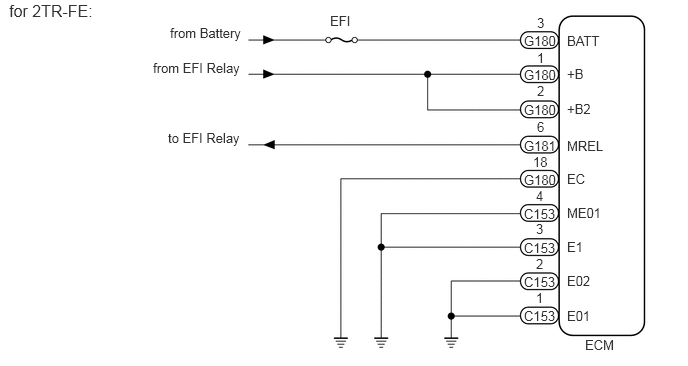
5.906,0.344 6.552,0.552 0.646,0.208 10 false BATT 5.906,0.688 6.552,0.896 0.646,0.208 10 false +B 5.906,1.052 6.552,1.26 0.646,0.208 10 false +B2 5.906,1.438 6.552,1.646 0.646,0.208 10 false MREL 5.906,2.844 6.552,3.052 0.646,0.208 10 false E02 5.906,3.208 6.552,3.417 0.646,0.208 10 false E01 5.906,2.135 6.552,2.344 0.646,0.208 10 false ME01 3.438,0.135 3.708,0.323 0.271,0.188 10 false EFI 1.771,0.26 2.583,0.469 0.813,0.208 10 false from Battery 1.594,0.625 2.958,0.854 1.365,0.229 10 false from EFI Relay 0.094,0.01 1.458,0.24 1.365,0.229 12 false for 2TR-FE: 1.75,1.354 2.938,1.583 1.188,0.229 10 false to EFI Relay 5.458,0.344 5.823,0.563 0.365,0.219 10 false G180 5.458,0.698 5.823,0.917 0.365,0.219 10 false G180 5.458,1.438 5.823,1.656 0.365,0.219 10 false G181 5.458,1.792 5.823,2.01 0.365,0.219 10 false G180 5.458,2.146 5.823,2.365 0.365,0.219 10 false C153 5.458,2.5 5.823,2.719 0.365,0.219 10 false C153 5.458,2.854 5.823,3.073 0.365,0.219 10 false C153 5.458,3.208 5.823,3.427 0.365,0.219 10 false C153 5.458,1.063 5.823,1.281 0.365,0.219 10 false G180 5.594,0.156 5.771,0.313 0.177,0.156 10 false 3 5.594,0.521 5.771,0.677 0.177,0.156 10 false 1 5.594,0.865 5.771,1.021 0.177,0.156 10 false 2 5.594,1.24 5.771,1.396 0.177,0.156 10 false 6 5.552,1.604 5.729,1.76 0.177,0.156 10 false 18 5.583,2.667 5.76,2.823 0.177,0.156 10 false 2 5.583,2.302 5.76,2.458 0.177,0.156 10 false 3 5.583,1.958 5.76,2.115 0.177,0.156 10 false 4 5.906,1.781 6.552,1.99 0.646,0.208 10 false EC 5.583,3.021 5.781,3.198 0.198,0.177 10 false 1 5.906,2.49 6.552,2.698 0.646,0.208 10 false E1 6.094,3.51 6.49,3.698 0.396,0.188 10 false ECM

CAUTION / NOTICE / HINT

NOTICE:

Inspect the fuses for circuits related to this system before performing the following inspection procedure.


PROCEDURE

1.CHECK HARNESS AND CONNECTOR (ECM - BATTERY AND BODY GROUND)
a.

for 1GR-FE and Manual Transmission System:

i.

Disconnect the C36, C37 and G55 ECM connectors.
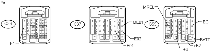
U148698E04
0.802,0.917 0.625,1.458 0.625,1.458 0.521,1.458 false 5.646,0.885 5.271,0.219 5.271,0.219 5.177,0.219 false 4.115,0.865 4.313,0.74 4.313,0.74 4.406,0.74 false 6.458,0.844 6.656,0.719 6.656,0.719 6.75,0.719 false 6.396,1.25 6.594,1.333 6.594,1.333 6.688,1.333 false 6.156,1.25 6.365,1.531 6.365,1.531 6.469,1.531 false 5.896,1.25 6.031,1.656 6.031,1.656 6.125,1.656 false 3.865,1.073 4.135,1.531 4.135,1.531 4.229,1.531 false 4.104,1.073 4.375,1.302 4.375,1.302 4.479,1.302 false 0.146,0.708 0.438,0.875 0.292,0.167 10 false C36 2.469,0.729 2.76,0.896 0.292,0.167 10 false C37 4.979,0.729 5.271,0.896 0.292,0.167 10 false G55 4.448,0.667 4.833,0.833 0.385,0.167 10 false ME01 0.333,1.385 0.531,1.552 0.198,0.167 10 false E1 0.042,0.01 0.24,0.177 0.198,0.167 10 false *a 4.792,0.156 5.208,0.323 0.417,0.167 10 false MREL 6.792,0.656 7.031,0.823 0.24,0.167 10 false EC 6.698,1.26 7.094,1.427 0.396,0.167 10 false BATT 6.479,1.458 6.875,1.625 0.396,0.167 10 false +B2 6.135,1.583 6.417,1.75 0.281,0.167 10 false +B 4.24,1.458 4.521,1.625 0.281,0.167 10 false E01 4.49,1.229 4.771,1.396 0.281,0.167 10 false E02

Text in Illustration
*a Front view of wire harness connector
(to ECM)
- -


ii.

Measure the resistance according to the value(s) in the table below.

Standard Resistance:
Tester Connection Condition Specified Condition
C36-12 (E1) - Body ground Always Below 1 Ω
C37-14 (E01) - Body ground Always Below 1 Ω
C37-15 (E02) - Body ground Always Below 1 Ω
C37-10 (ME01) - Body ground Always Below 1 Ω
G55-12 (EC) - Body ground Always Below 1 Ω


iii.

Measure the voltage according to the value(s) in the table below.

Standard Voltage:
Tester Connection Condition Specified Condition
G55-24 (BATT) - Body ground Always 11 to 14 V
G55-23 (+B2) - Body ground Battery positive (+) voltage applied to terminal G55-9 (MREL) 11 to 14 V
G55-22 (+B) - Body ground Battery positive (+) voltage applied to terminal G55-9 (MREL) 11 to 14 V


b.

for 1GR-FE and Automatic Transmission System:

i.

Disconnect the C36, C37, G55 and G56 ECM connectors.
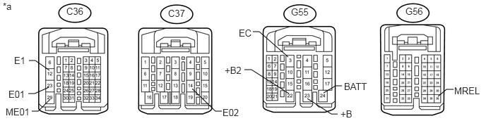
U170542E02
0.74,1.469 0.563,1.646 0.563,1.646 0.469,1.646 false 4.25,0.844 3.823,0.469 3.823,0.469 3.729,0.469 false 4.771,1.375 4.948,1.271 4.948,1.271 5.042,1.271 false 4.531,1.458 4.885,1.688 4.885,1.688 4.979,1.688 false 4.26,1.385 3.708,1.031 3.708,1.031 3.604,1.031 false 2.833,1.313 3.177,1.646 3.177,1.646 3.271,1.646 false 0.729,1.042 0.521,0.896 0.521,0.896 0.427,0.896 false 0.719,1.292 0.51,1.385 0.51,1.385 0.417,1.385 false 6.458,1.427 6.583,1.323 6.583,1.323 6.688,1.323 false 0.979,0.083 1.271,0.25 0.292,0.167 10 false C36 2.479,0.115 2.771,0.281 0.292,0.167 10 false C37 0.042,0.01 0.24,0.177 0.198,0.167 10 false *a 0.083,1.573 0.469,1.74 0.385,0.167 10 false ME01 4.292,0.094 4.583,0.26 0.292,0.167 10 false G55 3.521,0.406 3.76,0.573 0.24,0.167 10 false EC 5.073,1.198 5.469,1.365 0.396,0.167 10 false BATT 5.021,1.604 5.417,1.771 0.396,0.167 10 false +B 3.313,0.958 3.594,1.125 0.281,0.167 10 false +B2 3.281,1.583 3.563,1.75 0.281,0.167 10 false E02 5.979,0.083 6.271,0.25 0.292,0.167 10 false G56 6.698,1.26 7.115,1.427 0.417,0.167 10 false MREL 0.208,0.813 0.594,0.979 0.385,0.167 10 false E1 0.125,1.313 0.51,1.479 0.385,0.167 10 false E01

Text in Illustration
*a Front view of wire harness connector
(to ECM)
- -


ii.

Measure the resistance according to the value(s) in the table below.

Standard Resistance:
Tester Connection Condition Specified Condition
C36-12 (E1) - Body ground Always Below 1 Ω
C36-23 (E01) - Body ground Always Below 1 Ω
C37-14 (E02) - Body ground Always Below 1 Ω
C36-29 (ME01) - Body ground Always Below 1 Ω
G55-3 (EC) - Body ground Always Below 1 Ω


iii.

Measure the voltage according to the value(s) in the table below.

Standard Voltage:
Tester Connection Condition Specified Condition
G55-24 (BATT) - Body ground Always 11 to 14 V
G55-22 (+B2) - Body ground Battery positive (+) voltage applied to terminal G56-36 (MREL) 11 to 14 V
G55-23 (+B) - Body ground Battery positive (+) voltage applied to terminal G56-36 (MREL) 11 to 14 V


c.

for 1KD-FTV:

i.

Disconnect the C93, G57 and G58 ECM connectors.
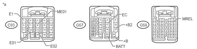
U170372E02
0.844,0.708 0.625,0.5 0.625,0.5 0.521,0.5 true 0.615,1.542 0.729,1.542 0.729,1.542 1.115,1.146 true 1.375,1.146 1.677,1.667 1.677,1.667 1.813,1.667 true 1.385,0.875 1.854,0.406 1.854,0.406 2.063,0.406 true 3.917,0.854 4.281,0.521 4.281,0.521 4.427,0.521 true 4.552,0.906 4.427,0.906 4.427,0.906 4.219,1.031 true 3.917,1.313 4.104,1.688 4.104,1.688 4.198,1.688 true 6.583,0.677 6.469,0.677 6.469,0.677 6.271,0.813 true 4.479,1.49 4.344,1.49 4.344,1.49 4.146,1.313 true 0.094,0.073 0.365,0.323 0.271,0.25 10 false *a 0.281,0.833 0.552,0.979 0.271,0.146 10 false C93 2.771,0.833 3.052,0.979 0.281,0.146 10 false G57 5.094,0.833 5.375,0.979 0.281,0.146 10 false G58 6.635,0.604 7.063,0.75 0.427,0.146 10 false MREL 4.438,0.458 4.865,0.604 0.427,0.146 10 false EC 4.563,0.823 4.99,0.969 0.427,0.146 10 false +B2 4.49,1.417 4.917,1.563 0.427,0.146 10 false +B 4.219,1.615 4.646,1.76 0.427,0.146 10 false BATT 2.073,0.344 2.5,0.49 0.427,0.146 10 false ME01 1.833,1.604 2.26,1.75 0.427,0.146 10 false E02 0.344,1.479 0.771,1.625 0.427,0.146 10 false E01 0.323,0.427 0.75,0.573 0.427,0.146 10 false E1

Text in Illustration
*a Front view of wire harness connector
(to ECM)
- -


ii.

Measure the resistance according to the value(s) in the table below.

Standard Resistance:
Tester Connection Condition Specified Condition
C93-1 (E1) - Body ground Always Below 1 Ω
C93-12 (E01) - Body ground Always Below 1 Ω
C93-13 (E02) - Body ground Always Below 1 Ω
C93-8 (ME01) - Body ground Always Below 1 Ω
G57-11 (EC) - Body ground Always Below 1 Ω


iii.

Measure the voltage according to the value(s) in the table below.

Standard Voltage:
Tester Connection Condition Specified Condition
G57-23 (BATT) - Body ground Always 11 to 14 V
G57-17 (+B2) - Body ground Battery positive (+) voltage applied to terminal G58-11 (MREL) 11 to 14 V
G57-24 (+B) - Body ground Battery positive (+) voltage applied to terminal G58-11 (MREL) 11 to 14 V


d.

for 1GD-FTV:

i.

Disconnect the C151, C152, G184 and G185 ECM connectors.
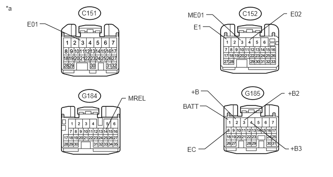
U170473E03
6.219,3.208 6.146,3.208 6.146,3.208 5.427,2.656 false 2.281,2.792 2.625,2.115 2.625,2.115 2.708,2.115 false 6.125,2.01 6.063,2.01 6.063,2.01 5.26,2.583 false 1.729,0.865 0.969,0.51 0.969,0.51 0.854,0.51 false 4.906,2.813 4.406,3.208 4.406,3.208 4.271,3.208 false 4.906,2.573 4.438,2.281 4.438,2.281 4.302,2.281 false 5.073,2.563 4.469,1.958 4.469,1.958 4.323,1.958 false 4.875,0.844 4.51,0.573 4.51,0.573 4.365,0.573 false 5.177,0.865 4.573,0.313 4.573,0.313 4.438,0.313 false 5.375,0.854 6.115,0.292 6.115,0.292 6.177,0.292 false 1.76,0.198 2.146,0.375 0.385,0.177 10 false C151 6.25,0.219 6.854,0.396 0.604,0.177 10 false E02 2.76,2.031 3.323,2.208 0.563,0.177 10 false MREL 4.042,0.24 4.49,0.417 0.448,0.177 10 false ME01 4.167,0.5 4.438,0.677 0.271,0.177 10 false E1 0.583,0.438 0.948,0.615 0.365,0.177 10 false E01 4.115,1.896 4.677,2.063 0.563,0.167 10 false +B 1.76,1.979 2.146,2.156 0.385,0.177 10 false G184 5.219,0.208 5.604,0.385 0.385,0.177 10 false C152 5.271,1.927 5.656,2.104 0.385,0.177 10 false G185 6.198,1.927 6.76,2.094 0.563,0.167 10 false +B2 6.25,3.115 6.813,3.281 0.563,0.167 10 false +B3 3.938,2.208 4.5,2.375 0.563,0.167 10 false BATT 4.031,3.135 4.594,3.302 0.563,0.167 10 false EC 0.125,0.094 0.49,0.271 0.365,0.177 10 false *a

Text in Illustration
*a Front view of wire harness connector
(to ECM)
- -


ii.

Measure the resistance according to the value(s) in the table below.

Standard Resistance:
Tester Connection Condition Specified Condition
C152-1 (E1) - Body ground Always Below 1 Ω
C151-3 (E01) - Body ground Always Below 1 Ω
C152-4 (E02) - Body ground Always Below 1 Ω
C152-3 (ME01) - Body ground Always Below 1 Ω
G185-8 (EC) - Body ground Always Below 1 Ω


iii.

Measure the voltage according to the value(s) in the table below.

Standard Voltage:
Tester Connection Condition Specified Condition
G185-1 (BATT) - Body ground Always 11 to 14 V
G185-2 (+B) - Body ground Battery positive (+) voltage applied to terminal G184-14 (MREL) 11 to 14 V
G185-3 (+B2) - Body ground Battery positive (+) voltage applied to terminal G184-14 (MREL) 11 to 14 V
G185-4 (+B3) - Body ground Battery positive (+) voltage applied to terminal G184-14 (MREL) 11 to 14 V


e.

for 2TR-FE:

i.

Disconnect the C153, G180 and C181 ECM connectors.
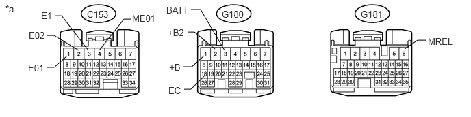
U170540E02
1.51,0.771 1.885,0.292 1.885,0.292 1.99,0.292 false 1.021,0.854 0.823,1.031 0.823,1.031 0.708,1.031 false 3.417,0.771 3.052,0.146 3.052,0.146 2.906,0.146 false 3.271,0.75 2.958,0.49 2.958,0.49 2.865,0.49 false 6.479,0.615 6.354,0.615 6.354,0.615 6.156,0.75 false 2.792,1.021 2.917,1.021 2.917,1.021 3.104,0.854 false 2.802,1.365 2.906,1.365 2.906,1.365 3.104,1.167 false 0.708,0.542 0.823,0.542 0.823,0.542 1.198,0.771 false 0.833,0.24 0.938,0.24 0.938,0.24 1.344,0.771 false 0.083,0.052 0.354,0.302 0.271,0.25 10 false *a 3.375,0.135 3.75,0.281 0.375,0.146 10 false G180 5.49,0.135 5.865,0.281 0.375,0.146 10 false G181 1.323,0.135 1.698,0.281 0.375,0.146 10 false C153 6.51,0.552 6.938,0.698 0.427,0.146 10 false MREL 2.531,0.073 2.958,0.219 0.427,0.146 10 false BATT 2.573,0.948 3,1.094 0.427,0.146 10 false +B 2.01,0.198 2.438,0.344 0.427,0.146 10 false ME01 0.427,0.958 0.854,1.104 0.427,0.146 10 false E01 2.552,0.417 2.979,0.563 0.427,0.146 10 false +B2 2.563,1.302 2.99,1.448 0.427,0.146 10 false EC 0.438,0.458 0.865,0.604 0.427,0.146 10 false E02 0.625,0.156 1.052,0.302 0.427,0.146 10 false E1

Text in Illustration
*a Front view of wire harness connector
(to ECM)
- -


ii.

Measure the resistance according to the value(s) in the table below.

Standard Resistance:
Tester Connection Condition Specified Condition
C153-3 (E1) - Body ground Always Below 1 Ω
C153-1 (E01) - Body ground Always Below 1 Ω
C153-2 (E02) - Body ground Always Below 1 Ω
C153-4 (ME01) - Body ground Always Below 1 Ω
G180-18 (EC) - Body ground Always Below 1 Ω


iii.

Measure the voltage according to the value(s) in the table below.

Standard Voltage:
Tester Connection Condition Specified Condition
G180-3 (BATT) - Body ground Always 11 to 14 V
G180-1 (+B) - Body ground Battery positive (+) voltage applied to terminal G181-6 (MREL) 11 to 14 V
G180-2 (+B2) - Body ground Battery positive (+) voltage applied to terminal G181-6 (MREL) 11 to 14 V


Result
Result Proceed to
OK (for 1GR-FE) A
OK (for 1KD-FTV) B
OK (for 2TR-FE) C
OK (for 1GD-FTV) D
NG E


A

B

C

D

E

REPAIR OR REPLACE HARNESS OR CONNECTOR