METER / GAUGE / DISPLAY METER / GAUGE SYSTEM B1501 Sub Fuel Sender Open Detected
DESCRIPTION
This DTC is stored when the combination meter detects a fuel sender gauge malfunction.
| DTC Code | DTC Detection Condition | Trouble Area |
|---|---|---|
| B1501 | Both conditions are met:
·
The voltage at the IG power supply terminal of the combination meter assembly is between 9.5 and 11.5 V. ·
Average input signal of fuel sender gauge is 630 Ω or more 3 times consecutively. |
·
Harness or connector ·
Combination meter assembly ·
Fuel tank vent tube assembly ·
Fuel sender gauge assembly |
- HINT:
-
Trouble code B1501 is only stored in vehicles equipped with a double tank.
WIRING DIAGRAM
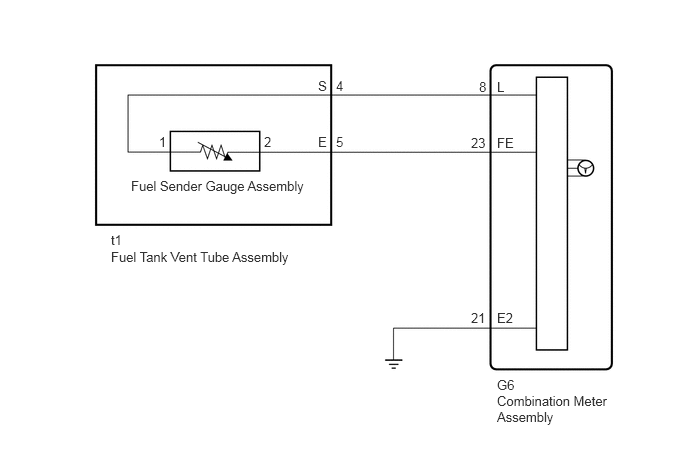
PROCEDURE
Using the GTS, read the Data List (See page Vehicle Interior>METER / GAUGE / DISPLAY>METER / GAUGE SYSTEM>DATA LIST / ACTIVE TEST).
| Tester Display | Measurement Item/Range | Normal Condition | Diagnostic Note |
|---|---|---|---|
| Fuel Input | Fuel input/Min.: 0, Max.: 127.5 | Current fuel level displayed | Unit: Liter |
- OK:
Fuel amount value displayed on the GTS is almost the same as the needle indication.
OK
NG
Disconnect the G6 combination meter assembly connector.
Disconnect the t1 fuel tank vent tube assembly connector.
Measure the resistance according to the value(s) in the table below.
- Standard Resistance:
Tester Connection Condition Specified Condition G6-8 (L) - t1-4 (S) Always Below 1 Ω G6-23 (FE) - t1-5 (E) Always Below 1 Ω G6-21 (E2) - Body ground Always Below 1 Ω G6-8 (L) or t1-4 (S) - Body ground Always 10 kΩ or higher G6-23 (FE) or t1-5 (E) - Body ground Always 10 kΩ or higher
OK
NG
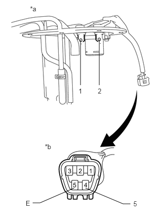
Remove the fuel tank vent tube assembly.
Measure the resistance according to the value(s) in the table below.
- Standard Resistance:
Tester Connection Condition Specified Condition 4 (S) - 1 Always Below 1 Ω 5 (E) - 2 Always Below 1 Ω
| *a | Fuel Tank Vent Tube Assembly |
| *b | Component without harness connected
(Fuel Tank Vent Tube Assembly) |
for 1GR-FE:
If it is necessary to replace the fuel tank vent tube assembly, refer to the following procedures (See page Engine / Hybrid System>1GR-FE (FUEL)>FUEL SENDER GAUGE ASSEMBLY (for Double Tank Type)>REMOVAL).
or 2TR-FE:
If it is necessary to replace the fuel tank vent tube assembly, refer to the following procedures (See page Engine / Hybrid System>2TR-FE (FUEL)>FUEL SENDER GAUGE ASSEMBLY (for Double Tank Type)>REMOVAL).
for 1KD-FTV:
If it is necessary to replace the fuel tank vent tube assembly, refer to the following procedures (See page Engine / Hybrid System>1KD-FTV (FUEL)>FUEL SENDER GAUGE ASSEMBLY (for Double Tank Type)>REMOVAL).
for 1GD-FTV:
If it is necessary to replace the fuel tank vent tube assembly, refer to the following procedures (See page Engine / Hybrid System>1GD-FTV (FUEL)>FUEL SENDER GAUGE ASSEMBLY (for Double Tank Type)>REMOVAL).
for 5L-E:
If it is necessary to replace the fuel tank vent tube assembly, refer to the following procedures (See page Engine / Hybrid System>5L-E (FUEL)>FUEL SENDER GAUGE ASSEMBLY>REMOVAL).
OK
NG
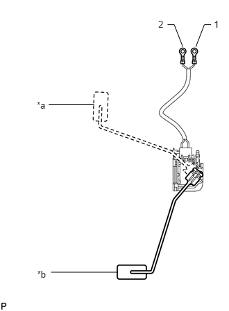
Remove the fuel sender gauge assembly.
Measure the resistance according to the value(s) in the table below.
- Standard Resistance:
Tester Connection Condition Specified Condition 1 - 2 Float level is F (upper) 13.5 to 16.5 Ω Float level is E (lower) 405.5 to 414.5 Ω
| *a | Float Level is F (Upper) |
| *b | Float Level is E (Lower) |
for 1GR-FE:
If it is necessary to replace the fuel sender gauge assembly, refer to the following procedures (See page Engine / Hybrid System>1GR-FE (FUEL)>FUEL SENDER GAUGE ASSEMBLY (for Double Tank Type)>REMOVAL).
or 2TR-FE:
If it is necessary to replace the fuel sender gauge assembly, refer to the following procedures (See page Engine / Hybrid System>2TR-FE (FUEL)>FUEL SENDER GAUGE ASSEMBLY (for Double Tank Type)>REMOVAL).
for 1KD-FTV:
If it is necessary to replace the fuel sender gauge assembly, refer to the following procedures (See page Engine / Hybrid System>1KD-FTV (FUEL)>FUEL SENDER GAUGE ASSEMBLY (for Double Tank Type)>REMOVAL).
for 1GD-FTV:
If it is necessary to replace the fuel sender gauge assembly, refer to the following procedures (See page Engine / Hybrid System>1GD-FTV (FUEL)>FUEL SENDER GAUGE ASSEMBLY (for Double Tank Type)>REMOVAL).
for 5L-E:
If it is necessary to replace the fuel sender gauge assembly, refer to the following procedures (See page Engine / Hybrid System>5L-E (FUEL)>FUEL SENDER GAUGE ASSEMBLY>REMOVAL).
OK
NG