RM27T0E
_58
Vehicle Interior
_053733
METER / GAUGE / DISPLAY
_0261083
TRIP SWITCH
G
METER / GAUGE / DISPLAY TRIP SWITCH INSPECTION
PROCEDURE

 84975
1.INSPECT TRIP SWITCH (w/o TAIL Cancel Switch)
a.
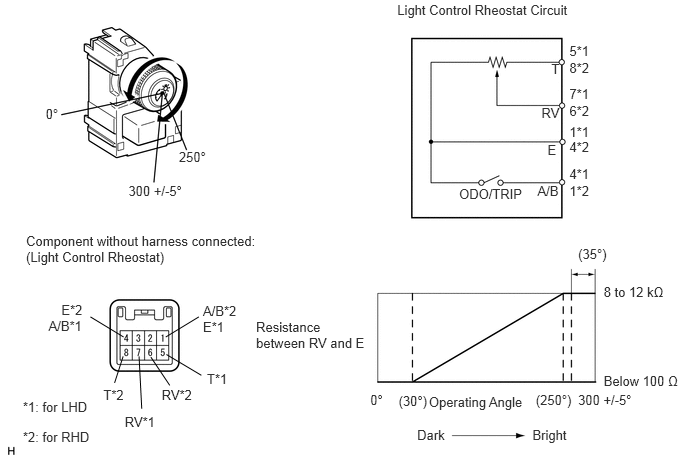
Inspect the light control rheostat.
i.
Measure the resistance according to the value(s) in the table below.
3.857,4.079 4.027,4.256
0.170,0.177
10
0°
4.152,4.09 4.518,4.246
0.367,0.156
10
(30°)
5.581,4.079 5.987,4.256
0.406,0.177
10
(250°)
6.022,4.079 6.622,4.256
0.600,0.177
10
300 +/-5°
6.288,2.954 6.951,3.131
0.663,0.177
10
8 to 12 kΩ
6.288,3.886 7.111,4.062
0.823,0.177
10
Below 100 Ω
6.022,2.563 6.362,2.718
0.340,0.156
10
(35°)
4.782,1.942 5.501,2.105
0.718,0.163
10
ODO/TRIP
2.667,3.325 3.885,3.634
1.218,0.309
10
Resistance between RV and E
4.467,4.103 5.526,4.266
1.059,0.163
10
Operating Angle
4.345,4.445 4.689,4.608
0.343,0.163
10
Dark
5.546,4.445 5.993,4.608
0.448,0.163
10
Bright
0.476,1.109 0.646,1.286
0.170,0.177
10
0°
1.863,1.557 2.214,1.734
0.350,0.177
10
250°
1.338,1.908 1.938,2.084
0.600,0.177
10
300 +/-5°
4.138,0.021 6.007,0.177
1.869,0.156
10
Light Control Rheostat Circuit
0.271,2.429 2.739,2.786
2.468,0.357
10
Component without harness connected: (Light Control Rheostat)
5.931,1.903 6.174,2.066
0.243,0.163
10
1*2
5.931,0.621 6.167,0.784
0.236,0.163
10
8*2
5.931,1.287 6.160,1.450
0.229,0.163
10
1*1
5.931,1.448 6.163,1.611
0.232,0.163
10
4*2
5.598,1.903 5.852,2.066
0.254,0.163
10
A/B
5.743,0.638 5.853,0.800
0.110,0.163
10
T
5.64,1.095 5.852,1.258
0.212,0.163
10
RV
5.703,1.476 5.853,1.639
0.150,0.163
10
E
2.114,3.155 2.525,3.318
0.411,0.163
10
A/B*2
1.076,4.028 1.346,4.191
0.270,0.163
10
T*2
1.684,4.028 2.072,4.191
0.388,0.163
10
RV*2
0.639,3.145 0.917,3.308
0.279,0.163
10
E*2
1.726,3.51 2.071,3.3
false
1.287,3.51 0.941,3.3
false
1.193,3.988 1.282,3.711
false
1.768,4.014 1.571,3.72
false
5.931,1.725 6.174,1.887
0.243,0.163
10
4*1
5.931,0.443 6.167,0.605
0.236,0.163
10
5*1
5.931,0.901 6.160,1.064
0.229,0.163
10
7*1
5.931,1.077 6.163,1.239
0.232,0.163
10
6*2
0.238,4.157 0.974,4.319
0.736,0.163
10
*1: for LHD
0.238,4.473 0.992,4.636
0.754,0.163
10
*2: for RHD
0.505,3.309 0.916,3.472
0.411,0.163
10
A/B*1
2.155,3.86 2.425,4.023
0.270,0.163
10
T*1
1.299,4.308 1.687,4.471
0.388,0.163
10
RV*1
2.114,3.328 2.393,3.490
0.279,0.163
10
E*1
2.097,3.909 1.733,3.692
false
1.448,3.711 1.476,4.257
false
- Standard Resistance:
for LHD Tester Connection Switch Condition Specified Condition 5 (T) - 1 (E) Always 8 to 12 kΩ 7 (RV) - 1 (E) Light control rheostat fully turned right → Light control rheostat fully turned left Below 100 Ω → 8 to 12 kΩ
for RHD Tester Connection Switch Condition Specified Condition 8 (T) - 4 (E) Always 8 to 12 kΩ 6 (RV) - 4 (E) Light control rheostat fully turned right → Light control rheostat fully turned left Below 100 Ω → 8 to 12 kΩ
b.
Inspect the ODO/TRIP switch.
i.
Measure the resistance according to the value(s) in the table below.
- Standard Resistance:
for LHD Tester Connection Switch Condition Specified Condition 4 (A/B) - 1 (E) ODO/TRIP switch on (Pushed) Below 1 Ω ODO/TRIP switch off (Not pushed) 1 MΩ or higher
for RHD Tester Connection Switch Condition Specified Condition 1 (A/B) - 4 (E) ODO/TRIP switch on (Pushed) Below 1 Ω ODO/TRIP switch off (Not pushed) 1 MΩ or higher
If the result is not as specified, replace the rheostat.
84975
2.INSPECT TRIP SWITCH (w/ TAIL Cancel Switch)
a.
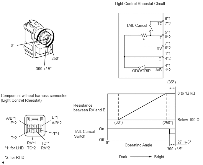
Inspect the light control rheostat.
i.
Measure the resistance according to the value(s) in the table below.
3.738,4.961 3.913,5.121
0.174,0.161
10
0°
4.035,4.239 4.381,4.400
0.346,0.161
10
(30°)
5.737,4.246 6.148,4.407
0.411,0.161
10
(250°)
5.896,5.173 6.496,5.334
0.600,0.161
10
300 +/-5°
6.267,4.933 6.794,5.093
0.526,0.161
10
27 +/-5°
5.908,2.81 6.244,2.971
0.336,0.161
10
(35°)
6.267,3.207 6.951,3.368
0.684,0.161
10
8 to 12 kΩ
6.267,4.144 7.092,4.304
0.825,0.161
10
Below 100 Ω
4.056,0.045 5.911,0.206
1.855,0.161
10
Light Control Rheostat Circuit
4.462,0.811 5.250,0.972
0.788,0.161
10
TAIL Cancel
0.378,1.519 0.553,1.679
0.174,0.161
10
0°
1.819,1.984 2.160,2.144
0.341,0.161
10
250°
1.268,2.343 1.868,2.504
0.600,0.161
10
300 +/-5°
0.031,3.289 2.539,3.630
2.508,0.341
10
Component without harness connected: (Light Control Rheostat)
2.592,3.639 3.794,3.966
1.202,0.327
10
Resistance between RV and E
2.613,4.564 3.398,4.877
0.786,0.313
10
TAIL Cancel Switch
3.496,4.473 3.732,4.633
0.237,0.161
10
On
3.496,4.851 3.705,5.012
0.209,0.161
10
Off
4.399,5.04 5.442,5.201
1.042,0.161
10
Operating Angle
4.203,5.457 4.544,5.618
0.341,0.161
10
Dark
5.443,5.457 5.874,5.618
0.431,0.161
10
Bright
5.551,0.746 5.763,0.909
0.212,0.163
10
TC
1.828,4.256 2.221,4.418
0.393,0.163
10
A/B*2
0.383,4.789 0.630,4.952
0.247,0.163
10
T*2
1.45,5.15 1.822,5.313
0.372,0.163
10
RV*2
0.371,4.263 0.624,4.425
0.253,0.163
10
E*2
0.955,5.141 1.327,5.303
0.372,0.163
10
TC*2
1.463,4.453 1.782,4.26
false
0.987,4.453 0.668,4.26
false
1.001,4.639 0.682,4.831
false
1.18,4.654 1.145,4.943
false
1.291,4.654 1.596,4.952
false
4.664,2.419 5.382,2.582
0.718,0.163
10
ODO/TRIP
5.822,2.39 6.065,2.553
0.243,0.163
10
1*2
5.822,1.22 6.058,1.383
0.236,0.163
10
8*2
5.822,1.605 6.051,1.768
0.229,0.163
10
6*2
5.822,1.977 6.054,2.140
0.232,0.163
10
4*2
5.489,2.39 5.743,2.553
0.254,0.163
10
A/B
5.634,1.251 5.744,1.413
0.110,0.163
10
T
5.531,1.638 5.743,1.801
0.212,0.163
10
RV
5.594,2.005 5.743,2.168
0.150,0.163
10
E
5.822,2.225 6.065,2.388
0.243,0.163
10
4*1
5.822,1.056 6.058,1.218
0.236,0.163
10
5*1
5.822,1.444 6.051,1.607
0.229,0.163
10
7*1
5.822,1.816 6.054,1.978
0.232,0.163
10
1*1
0.166,5.148 0.902,5.310
0.736,0.163
10
*1: for LHD
0.166,5.478 0.920,5.641
0.754,0.163
10
*2: for RHD
5.822,0.576 6.058,0.739
0.236,0.163
10
6*1
5.822,0.747 6.058,0.910
0.236,0.163
10
7*2
0.217,4.094 0.609,4.257
0.393,0.163
10
A/B*1
1.882,4.642 2.129,4.805
0.247,0.163
10
T*1
0.955,4.972 1.327,5.135
0.372,0.163
10
RV*1
1.828,4.066 2.081,4.229
0.253,0.163
10
E*1
1.45,4.975 1.822,5.138
0.372,0.163
10
TC*1
1.445,4.605 1.862,4.707
false
- Standard Resistance:
for LHD Tester Connection Switch Condition Specified Condition 5 (T) - 6 (TC) TAIL cancel switch off → on 1 MΩ or higher → Below 100 Ω 5 (T) - 1 (E) Always 8 to 12 kΩ 7 (RV) - 1 (E) Light control rheostat fully turned right → Light control rheostat fully turned left Below 100 Ω → 8 to 12 kΩ
for RHD Tester Connection Switch Condition Specified Condition 7 (TC) - 8 (T) TAIL cancel switch off → on 1 MΩ or higher → Below 1 Ω 8 (T) - 4 (E) Always 8 to 12 kΩ 6 (RV) - 4 (E) Light control rheostat fully turned right → Light control rheostat fully turned left Below 100 Ω → 8 to 12 kΩ
b.
Inspect the ODO/TRIP switch.
i.
Measure the resistance according to the value(s) in the table below.
- Standard Resistance:
for LHD Tester Connection Switch Condition Specified Condition 4 (A/B) - 1 (E) ODO/TRIP switch on (Pushed) Below 1 Ω ODO/TRIP switch off (Not pushed) 1 MΩ or higher
for RHD Tester Connection Switch Condition Specified Condition 1 (A/B) - 4 (E) ODO/TRIP switch on (Pushed) Below 1 Ω ODO/TRIP switch off (Not pushed) 1 MΩ or higher
If the result is not as specified, replace the rheostat.