HEATING / AIR CONDITIONING AIR CONDITIONING PANEL REASSEMBLY
CAUTION / NOTICE / HINT
- HINT:
- ·
Use the same procedure for RHD and LHD vehicles.
·The procedure listed below is for LHD vehicles.
PROCEDURE

 55904A
1.INSTALL HEATER CONTROL HOUSING SUB-ASSEMBLY (except G.C.C.)
Align the axis of the heater control housing sub-assembly gear with the encoder hole and insert the gear.
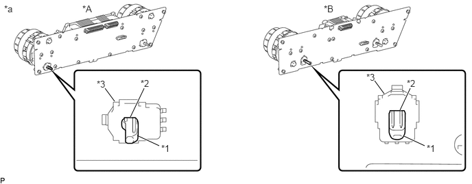
| *A | for Automatic Air Conditioning System | *B | for Manual Air Conditioning System |
| *1 | Gear Axis | *2 | Encoder Hole |
| *3 | Metal Cover | - | - |
| *a | Procedure Necessary to Prevent Electrostatic Discharge | - | - |
- NOTICE:
- ·
Do not touch any IC, circuit trace or circuit element without taking measures to prevent electrostatic discharge.
·Insert the gear of the heater control housing sub-assembly perpendicular to the No. 1 center cluster module circuit sub-assembly.
·The metal cover of the encoder can easily come off, so hold the cover in place while inserting the gear.
·Do not place excessive force on the dials of the heater control housing sub-assembly.
·Do not allow oil, grease or other foreign matter to contact the heater control housing sub-assembly and prevent it from being damaged.
·After installing the heater control housing sub-assembly with the screws, remove the tape fixing the dials in place from the new heater control housing sub-assembly.
Check that the slit or hole of the gear and the hole of the housing are positioned as shown in the illustration.
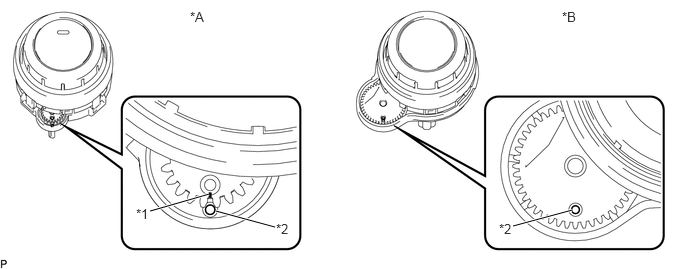
| *A | for Automatic Air Conditioning System | *B | for Manual Air Conditioning System |
| *1 | Slit | *2 | Hole |
Align the positioning pins on the heater control housing sub-assembly with the holes on the circuit board of the No. 1 center cluster module circuit sub-assembly, and then install the heater control housing sub-assembly to the center cluster module circuit with the 2 screws.
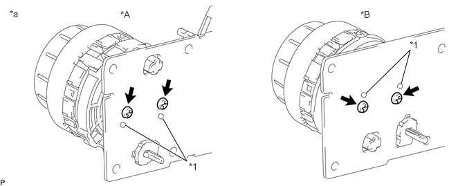
| *A | for Automatic Air Conditioning System | *B | for Manual Air Conditioning System |
| *1 | Positioning Pin | - | - |
| *a | Procedure Necessary to Prevent Electrostatic Discharge | - | - |
- NOTICE:
- ·
Be careful not to break the positioning pins on the heater control housing sub-assembly.
·Be careful not to damage the circuit board of the No. 1 center cluster module circuit sub-assembly.
2.INSTALL CONTROL KNOB SUB-ASSEMBLY
for Automatic Air Conditioning System:
Install the control knob sub-assembly.
Install the control knob sub-assembly and No. 1 center cluster module circuit sub-assembly to the front air conditioning panel sub-assembly.
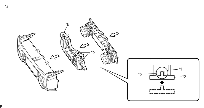
| *1 | Front Air Conditioning Panel Sub-assembly | *2 | Control Knob Sub-assembly |
| *a | Procedure Necessary to Prevent Electrostatic Discharge | *b | Confirm Correct Engagement |
- HINT:
-
Position the control knob sub-assembly so that the knobs face upwards and, while holding the front air conditioning panel sub-assembly parallel to the control knob sub-assembly, place the front air conditioning panel sub-assembly onto the control knob sub-assembly to install it.
- NOTICE:
- ·
Be sure not to allow skin oils, grease, foreign matter, etc. to adhere to the parts and be sure not to damage the parts.
·When installing the control knob sub-assembly and No. 1 center cluster module circuit sub-assembly to the front air conditioning panel sub-assembly, make sure that the ribs are properly engaged as shown in the illustration.
·Do not apply excessive force to the knobs when installing the control knob sub-assembly as the knobs break easily.
·Do not touch any IC, circuit trace or circuit element without taking measures to prevent electrostatic discharge.
Install the 6 screws.
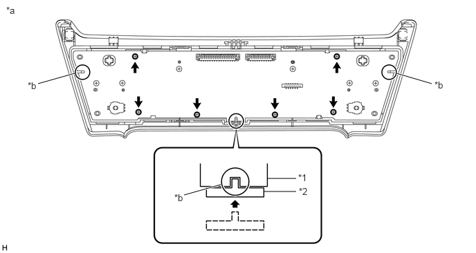
| *1 | No. 1 Center Cluster Module Circuit Sub-assembly | *2 | Front Air Conditioning Panel Sub-assembly |
| *a | Procedure Necessary to Prevent Electrostatic Discharge | *b | Confirm Correct Engagement |
- NOTICE:
- ·
Be sure not to allow skin oils, grease, foreign matter, etc. to adhere to the parts and be sure not to damage the parts.
·Do not touch any IC, circuit trace or circuit element without taking measures to prevent electrostatic discharge.
·Do not damage the No. 1 center cluster module circuit sub-assembly when tightening the screws.
for Manual Air Conditioning System:
Install the control knob sub-assembly.
Install the control knob sub-assembly and No. 1 center cluster module circuit sub-assembly to the front air conditioning panel sub-assembly.
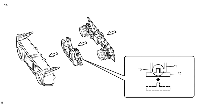
| *1 | Front Air Conditioning Panel Sub-assembly | *2 | Control Knob Sub-assembly |
| *a | Procedure Necessary to Prevent Electrostatic Discharge | *b | Confirm Correct Engagement |
- NOTICE:
- ·
Be sure not to allow skin oils, grease, foreign matter, etc. to adhere to the parts and be sure not to damage the parts.
·When installing the knob sub-assembly and No. 1 center cluster module circuit sub-assembly to the front case sub-assembly, make sure that the ribs are properly engaged as shown in the illustration.
·Do not apply excessive force to the knobs when installing the knob sub-assembly as the knobs break easily.
·Do not touch any IC, circuit trace or circuit element without taking measures to prevent electrostatic discharge.
Install the 6 screws.
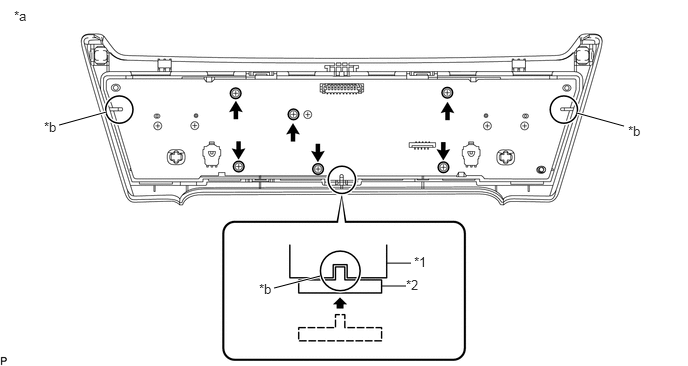
| *1 | No. 1 Center Cluster Module Circuit Sub-assembly | *2 | Front Air Conditioning Panel Sub-assembly |
| *a | Procedure Necessary to Prevent Electrostatic Discharge | *b | Confirm correct engagement |
- NOTICE:
- ·
Be sure not to allow skin oils, grease, foreign matter, etc. to adhere to the parts and be sure not to damage the parts.
·Do not touch any IC, circuit trace or circuit element without taking measures to prevent electrostatic discharge.
·Do not damage the No. 1 center cluster module circuit sub-assembly when tightening the screws.
3.INSTALL NO. 2 CENTER CLUSTER MODULE CIRCUIT SUB-ASSEMBLY
Install the No. 2 center cluster module circuit sub-assembly to the rear air conditioning panel sub-assembly.
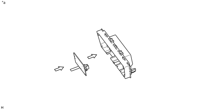
| *a | Procedure Necessary to Prevent Electrostatic Discharge | - | - |
- NOTICE:
- ·
When installing the No. 2 center cluster module circuit sub-assembly to the rear case sub-assembly, make sure that the ribs are properly engaged as shown in the illustration.
·Do not touch any IC, circuit trace or circuit element without taking measures to prevent electrostatic discharge.
Install the 3 screws.
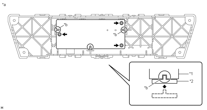
| *1 | No. 2 Center Cluster Module Circuit Sub-assembly | *2 | Rear Air Conditioning Panel Sub-assembly |
| *a | Procedure Necessary to Prevent Electrostatic Discharge | *b | Confirm correct engagement |
- NOTICE:
- ·
Do not touch any IC, circuit trace or circuit element without taking measures to prevent electrostatic discharge.
·Do not damage the No. 2 center cluster module circuit sub-assembly when tightening the screws.
Pull back the lock of the connector to unlock it.
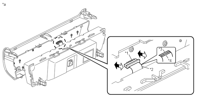
| *1 | Connector | *2 | Flexible Ribbon Cable |
| *3 | Blue Tape | *4 | Black Line |
| *a | Procedure Necessary to Prevent Electrostatic Discharge | - | - |

|
Lock | 
|
Unlock |
Connect the flexible ribbon cable, and then push in the lock to lock the connector.
- NOTICE:
- ·
Make sure that the flexible ribbon cable is connected securely and the lock of the connector is locked securely.
·Make sure that the black line on the flexible ribbon cable is not visible after locking the connector.
·When disconnecting the connector, do not pull it with excessive force.
·Do not pull the flexible ribbon cable after connecting it.
·Do not touch any IC, circuit trace or circuit element without taking measures to prevent electrostatic discharge.
Attach the 4 claws to install the rear air conditioning panel sub-assembly together with the No. 2 center cluster module circuit sub-assembly to the front air conditioning panel sub-assembly.
- NOTICE:
- ·
Make sure that the flexible ribbon cable does not get pinched between the front air conditioning panel and rear air conditioning panel when installing the rear air conditioning panel.
Install the 4 screws.