Home › Vehicle Interior › HEATING / AIR CONDITIONING › COMBUSTION TYPE POWER HEATER SYSTEM
RM27T0E _58 Vehicle Interior _053739 HEATING / AIR CONDITIONING _0261205 COMBUSTION TYPE POWER HEATER SYSTEM D

HEATING / AIR CONDITIONING  COMBUSTION TYPE POWER HEATER SYSTEM  SYSTEM DESCRIPTION  


GENERAL


a.

While the engine offers excellent combustion efficiency, it generates low levels of heat. Therefore, depending on the operating condition, the engine coolant temperature may be too low to ensure proper heating. In this case, the heater assembly is used to provide the additional heating.


b.

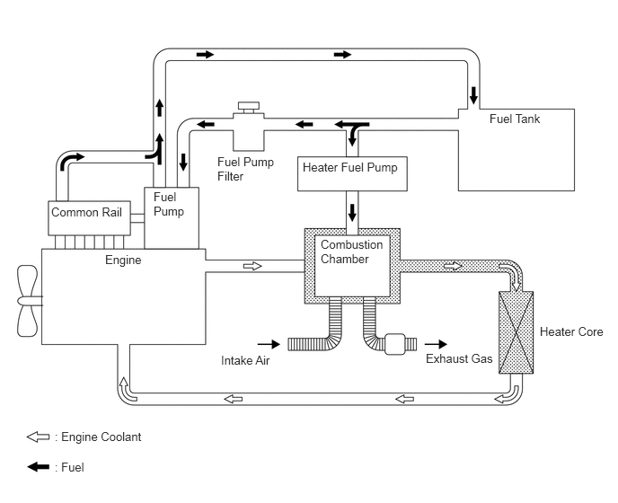
This heater system provides a heater assembly between the engine and heater core. Air and fuel are introduced into the combustion chamber of the heater and a glow plug is used to ignite this mixture. By heating the engine coolant that flows around the combustion chamber, this system ensures proper heating.
E183958E04
0.635,4.979 1.75,5.323 1.115,0.344 10 false : Engine Coolant 0.635,5.333 1.063,5.719 0.427,0.385 10 false : Fuel 2.521,1.792 3.26,2.125 0.74,0.333 10 false Fuel Pump Filter 0.594,2.375 1.49,2.708 0.896,0.333 10 false Common Rail 1.781,2.198 2.229,2.844 0.448,0.646 10 false Fuel Pump 1.219,2.927 1.74,3.313 0.521,0.385 10 false Engine 2.563,4.094 3.229,4.469 0.667,0.375 10 false Intake Air 4.938,4.073 5.792,4.427 0.854,0.354 10 false Exhaust Gas 3.51,1.854 4.698,2.177 1.188,0.323 10 false Heater Fuel Pump 5.677,1.292 6.375,1.646 0.698,0.354 10 false Fuel Tank 6.26,3.76 7.115,4.156 0.854,0.396 10 false Heater Core 3.719,2.75 4.5,3.385 0.781,0.635 10 false Combustion Chamber


HEATER ASSEMBLY


a.

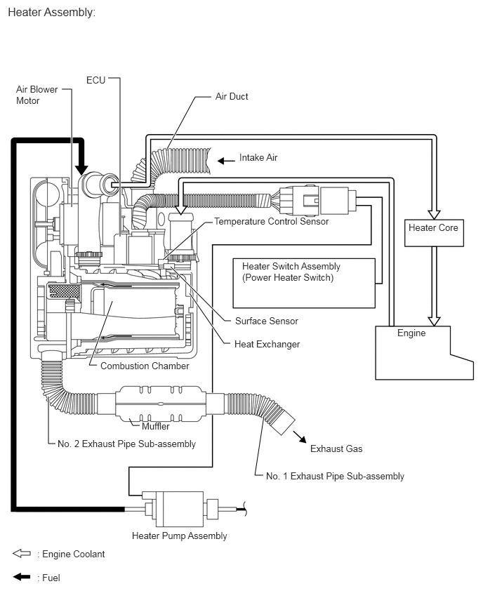
This system, which consists of a heater assembly, heater switch assembly (power heater switch) and heater pump assembly, operates when the engine is idling and the heater switch assembly (power heater switch) is turned on.

·

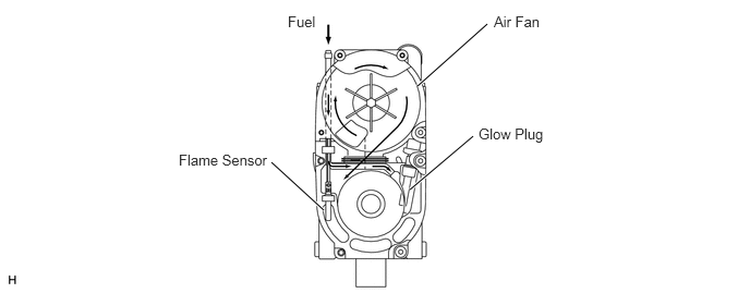
The heater assembly consists of an ECU, flame sensor, surface sensor, temperature control sensor, glow plug and air blower motor. It cannot be disassembled.

·

The ECU in the heater assembly controls this system in accordance with the signals received from the sensors and switches.
E184678E03
1.063,3.073 1.063,1.323 1.063,1.323 0.917,1.323 true 1.781,3.51 1.781,1.156 1.781,1.156 1.604,1.156 true 2.479,2.208 2.896,1.438 2.896,1.438 3.135,1.438 true 2.417,3.854 3.042,3.302 3.042,3.302 3.156,3.302 true 2.531,3.958 3.333,4.76 3.333,4.76 3.427,4.76 true 2.813,4.354 3.323,5.094 3.323,5.094 3.417,5.094 true 1.667,4.469 1.323,5.417 1.323,5.417 1.438,5.417 true 1.917,6.208 1.969,6.313 1.969,6.313 2.073,6.313 false 0.719,5.885 0.719,6.583 0.719,6.583 0.823,6.583 true 3.917,6.167 3.781,7.052 3.781,7.052 3.906,7.052 true 0.552,8.135 1.667,8.333 1.115,0.198 10 false : Engine Coolant 0.552,8.49 1,8.688 0.448,0.198 10 false : Fuel 3.594,3.865 5.146,4.229 1.552,0.365 10 false Heater Switch Assembly (Power Heater Switch) 6.063,3.292 6.854,3.458 0.792,0.167 10 false Heater Core 5.896,4.854 6.438,5.042 0.542,0.188 10 false Engine 3.198,1.344 3.76,1.521 0.563,0.177 10 false Air Duct 1.281,1.104 1.667,1.24 0.385,0.135 10 false ECU 0.24,1.24 0.927,1.573 0.688,0.333 10 false Air Blower Motor 3.552,2.25 4.208,2.417 0.656,0.167 10 false Intake Air 3.177,3.198 4.99,3.406 1.813,0.208 10 false Temperature Control Sensor 3.49,4.677 4.531,4.833 1.042,0.156 10 false Surface Sensor 4.604,6.573 5.458,6.729 0.854,0.156 10 false Exhaust Gas 3.479,5.021 4.542,5.177 1.063,0.156 10 false Heat Exchanger 3.948,6.979 6.135,7.177 2.188,0.198 10 false No. 1 Exhaust Pipe Sub-assembly 0.854,6.5 3.042,6.698 2.188,0.198 10 false No. 2 Exhaust Pipe Sub-assembly 1.958,7.865 3.51,8.031 1.552,0.167 10 false Heater Pump Assembly 2.104,6.24 2.604,6.396 0.5,0.156 10 false Muffler 1.49,5.344 2.885,5.521 1.396,0.177 10 false Combustion Chamber 0.115,0.073 2.958,0.323 2.844,0.25 12 false Heater Assembly:

E177180E06
3.99,0.823 4.656,0.229 true 3.917,1.813 4.521,1.302 true 2.594,1.552 3.094,2.01 true 2.75,0.125 3.104,0.323 0.354,0.198 10 Fuel 4.719,0.125 5.24,0.292 0.521,0.167 10 Air Fan 4.573,1.198 5.271,1.396 0.698,0.198 10 Glow Plug 1.708,1.448 2.615,1.635 0.906,0.188 10 Flame Sensor


OPERATION


a.

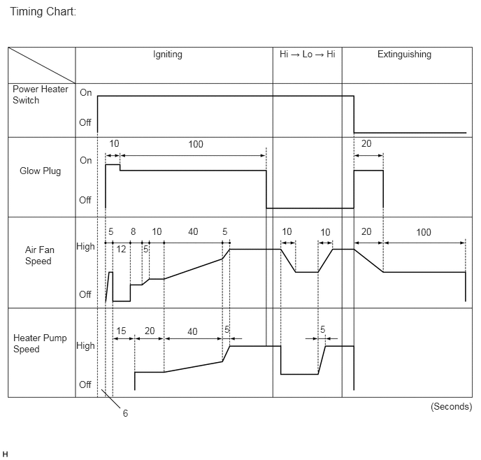
When the engine is idling, turning the heater switch assembly (power heater switch) on causes the air fan to operate for several seconds for verification purposes. Then, the glow plug starts to preheat the combustion chamber. After that, the heater pump assembly and air fan turn on in order to start low combustion. The heater pump assembly speed is then increased in steps, and this is accompanied by a gradual increase in the speed of the air fan, thus leading to high combustion.


b.

When the engine switch is turned off or the power heater switch is turned off, the heater pump stops, causing the combustion to stop. For the purpose of after-purge, current is applied again to the glow plug, and the air fan is activated for several seconds. Then, the entire system comes to a stop.
E145177E10
1.51,5.802 1.792,6.083 false 0.146,0.063 1.219,0.271 1.073,0.208 12 false Timing Chart: 2.281,0.719 2.781,0.927 0.5,0.208 10 false Igniting 4.167,0.719 5.146,0.917 0.979,0.198 10 false Hi → Lo → Hi 5.625,0.719 6.521,0.885 0.896,0.167 10 false Extinguishing 0.188,1.24 1.094,1.563 0.906,0.323 10 false Power Heater Switch 0.292,2.458 0.99,2.677 0.698,0.219 10 false Glow Plug 0.375,3.635 0.896,4.01 0.521,0.375 10 false Air Fan Speed 1.188,1.292 1.5,1.458 0.313,0.167 10 false On 1.188,2.302 1.5,2.469 0.313,0.167 10 false On 1.177,1.74 1.49,1.906 0.313,0.167 10 false Off 1.177,2.896 1.49,3.063 0.313,0.167 10 false Off 1.177,4.302 1.49,4.469 0.313,0.167 10 false Off 1.177,5.646 1.49,5.813 0.313,0.167 10 false Off 0.198,4.948 1.063,5.333 0.865,0.385 10 false Heater Pump Speed 1.135,3.583 1.469,3.771 0.333,0.188 10 false High 1.135,5.063 1.469,5.25 0.333,0.188 10 false High 1.833,6.073 1.979,6.292 0.146,0.219 10 false 6 6.417,5.969 7.125,6.156 0.708,0.188 10 false (Seconds) 1.625,2.052 1.823,2.25 0.198,0.198 10 false 10 4.198,3.365 4.396,3.563 0.198,0.198 10 false 10 4.771,3.375 4.969,3.573 0.198,0.198 10 false 10 2.26,3.365 2.458,3.563 0.198,0.198 10 false 10 2.802,3.365 3,3.563 0.198,0.198 10 false 40 2.792,4.854 2.99,5.052 0.198,0.198 10 false 40 2.802,2.063 3.094,2.26 0.292,0.198 10 false 100 6.198,3.375 6.49,3.573 0.292,0.198 10 false 100 5.385,2.052 5.677,2.25 0.292,0.198 10 false 20 5.385,3.365 5.677,3.563 0.292,0.198 10 false 20 2.156,4.844 2.448,5.042 0.292,0.198 10 false 20 1.615,3.365 1.781,3.552 0.167,0.188 10 false 5 2.135,3.625 2.302,3.813 0.167,0.188 10 false 5 3.313,3.365 3.479,3.552 0.167,0.188 10 false 5 4.771,4.823 4.938,5.01 0.167,0.188 10 false 5 3.344,4.823 3.51,5.01 0.167,0.188 10 false 5 1.729,3.625 1.948,3.865 0.219,0.24 10 false 12 1.729,4.844 1.948,5.083 0.219,0.24 10 false 15 1.948,3.365 2.094,3.531 0.146,0.167 10 false 8


c.

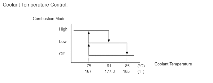
While the system is in operation, it controls the heater pump speed, switches between high combustion and low combustion, and always keeps the engine coolant temperature between 75°C (167°F) and 85°C (185°F). If the coolant temperature exceeds 85°C (185°F), the heater pump assembly stops automatically to stop the combustion. Thereafter, when the engine coolant temperature reaches 75°C (167°F) or below, ignition occurs again. The operation of the glow plug, air fan and heater pump assembly during extinguishing and re-igniting is the same as when these are operated by switch as mentioned previously.
E326699E02
0.094,0.052 2.51,0.271 2.417,0.219 12 false Coolant Temperature Control: 1.104,0.542 2.375,0.76 1.271,0.219 10 false Combustion Mode 1.99,0.896 2.385,1.083 0.396,0.188 10 false High 1.99,1.313 2.385,1.5 0.396,0.188 10 false Low 1.99,1.729 2.385,1.917 0.396,0.188 10 false Off 2.917,2.135 3.156,2.323 0.24,0.188 10 false 75 3.594,2.135 3.833,2.323 0.24,0.188 10 false 81 4.208,2.135 4.448,2.323 0.24,0.188 10 false 85 2.854,2.323 3.156,2.51 0.302,0.188 10 false 167 3.521,2.323 3.927,2.51 0.406,0.188 10 false 177.8 4.135,2.323 4.49,2.51 0.354,0.188 10 false 185 4.625,2.135 5.021,2.385 0.396,0.25 10 false (°C) 5.198,2.073 6.688,2.323 1.49,0.25 10 false Coolant Temperature 4.625,2.323 5.021,2.573 0.396,0.25 10 false (°F)


FAIL-SAFE


a.

If the glow plug breaks, the ECU detects the problem and stops automatic operation to prevent heater assembly operation.


b.

If the temperature detected by the temperature control sensor or surface sensor exceeds 125°C (257°F), the ECU determines that the heater assembly is operating without engine coolant and automatically stops the system.


c.

If the difference in temperature detected by the temperature control sensor and surface sensor exceeds 25°C (77°F), the ECU determines that the flow volume of the engine coolant is insufficient and automatically stops the system.


d.

If the temperature of the exhaust gas detected by the flame sensor is low, the ECU determines that a non-ignition or a misfiring condition exists and automatically stops the system.


e.

If an open or short circuit exists in the sensors or actuators, the ECU automatically stops the system.


f.

If the air fan seizes, the ECU automatically stops the system.