HEATING / AIR CONDITIONING COMBUSTION TYPE POWER HEATER SYSTEM 047 Short in Heater Fuel Pump Circuit 048 Heater Fuel Pump Malfunction 049 Heater Fuel Pump Output Error
DESCRIPTION
| DTC Code | DTC Detection Condition | Trouble Area |
|---|---|---|
| 047 | A short is detected in the heater pump circuit. | ·
Harness or connector ·
Heater pump assembly ·
Heater assembly |
| 048 | Operation stop of the heater pump is detected. (Open in the circuit) | ·
Harness or connector ·
Heater pump assembly ·
Heater assembly |
| 049 | An error is detected in output to the heater pump. | ·
Harness or connector ·
Heater pump assembly ·
Heater assembly |
WIRING DIAGRAM
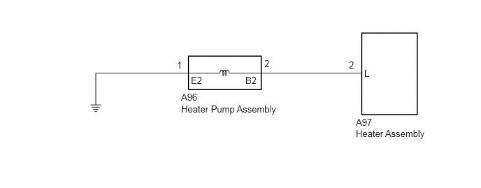
PROCEDURE
Disconnect the A97 heater assembly connector.
Disconnect the A96 heater pump assembly connector.
Measure the resistance according to the value(s) in the table below.
- Standard Resistance:
Tester Connection Condition Specified Condition A97-2 (L) - A96-2 (B2) Always Below 1 Ω A97-2 (L) - Body ground Always 10 kΩ or higher
OK
NG
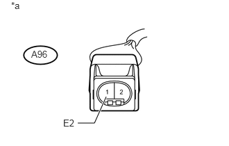
Disconnect the heater pump assembly connector.
Measure the resistance according to the value(s) in the table below.
- Standard Resistance:
Tester Connection Condition Specified Condition A96-1 (E2) - Body ground Always Below 1 Ω
| *a | Front view of wire harness connector
(to Heater Pump Assembly) |
OK
NG
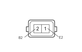
Remove the heater pump assembly (See page Vehicle Interior>HEATING / AIR CONDITIONING>HEATER ASSEMBLY>REMOVAL).
Measure the resistance according to the value(s) in the table below.
- Standard Resistance:
Tester Connection Condition Specified Condition 2 (B2) - 1 (E2) Always 9 to 12 Ω
Inspect the heater pump assembly operation.
Connect a positive (+) lead from the battery to terminal 2 (B2) and a negative (-) lead to terminal 1 (E2), and check the pressure of the hose by hand.
- NOTICE:
-
This inspection must be done quickly (within 10 seconds) to prevent damage to the heater pump assembly.
| Result | Proceed to |
|---|---|
| The pressure is applied to the hose | A |
| The pressure is not applied to the hose | B |
A
B