RM27T0E
_58
Vehicle Interior
_053740
POWER OUTLETS (INT)
_0261206
VOLTAGE INVERTER(for 5 Door)
G
POWER OUTLETS (INT) VOLTAGE INVERTER(for 5 Door) ON-VEHICLE INSPECTION
PROCEDURE

 86210A
1.INSPECT VOLTAGE INVERTER ASSEMBLY
- HINT:
-
Remove interior parts so that the voltage inverter can be seen.
a.
0.182,0.782 0.521,0.934
0.339,0.152
10
GND
0.3,1.676 0.473,1.839
0.173,0.162
10
IG
0.581,0.866 1.124,1.352
false
0.511,1.768 1.118,1.571
false
2.636,1.19 2.900,1.372
0.264,0.181
10
Q17
0.108,0.086 0.270,0.259
0.162,0.173
10
*a
Disconnect the voltage inverter connector.
b.
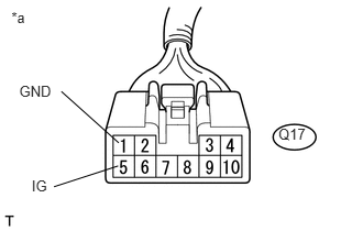
Measure the voltage according to the value(s) in the table below.
- Standard Voltage:
Tester Connection Switch Condition Specified Condition Q17-5 (IG) - Q17-1 (GND) Ignition switch ON 11 to 14 V Q17-1 (GND) - Body ground Always Below 1 V
If the result is not as specified, repair or replace the harness or connector.
| *a | Front view of wire harness connector
(to Voltage Inverter Assembly) |
c.
0.138,0.711 0.443,0.876
0.306,0.166
10
AC1
0.332,1.562 0.636,1.715
0.304,0.153
10
AC2
1.001,0.676 0.495,0.8
false
1.402,0.966 0.711,1.657
false
0.111,0.07 0.294,0.223
0.183,0.153
10
*a
2.594,1.022 2.858,1.203
0.264,0.181
10
Q17
Reconnect the voltage inverter connector.
d.
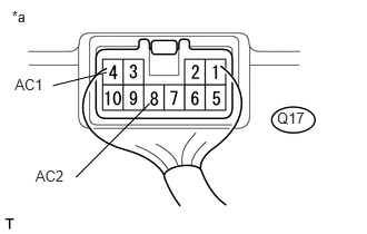
Measure the voltage according to the value(s) in the table below.
- Standard Voltage:
Tester Connection Switch Condition Specified Condition Q17-4 (AC1) - Q17-8 (AC2) Ignition switch ON, main switch on AC 220 V
If the result is not as specified, replace the voltage inverter assembly.
| *a | Component with harness connected
(Voltage Inverter Assembly) |