INTERIOR PANELS / TRIM FRONT CONSOLE BOX(w/ Refrigerated Cool Box) REASSEMBLY
PROCEDURE

 88306
1.INSTALL NO. 1 COOLER BLOWER MOTOR SUB-ASSEMBLY
Attach the 3 claws to install the No. 1 cooler blower motor sub-assembly.
88361
2.INSTALL NO. 1 COOLER BLOWER FAN
Align the fan motor splines and install the No. 1 cooler blower fan.
- NOTICE:
-
Be careful not to damage the fan splines.
Attach the 4 claws to install the blower fan cover.
88501D
3.INSTALL NO. 2 COOLER EVAPORATOR SUB-ASSEMBLY
Tighten the 2 nuts and install the liquid tube, cooler magnet valve and No. 2 cooler evaporator sub-assembly.
- Torque:
- 13.3 N*m (136 kgf*cm, 10 ft.*lbf)
Attach the 2 claws.
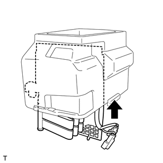
Install the cooler evaporator assembly.
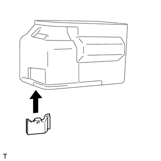
Install the cooling unit case.
Install the 4 bolts.
Install the 5 holding springs.
Install the air duct with the 3 screws and 5 bolts.
88522
4.INSTALL COOLING UNIT DOOR
Install the cooling unit door with the 8 screws and 2 bolts.
Install new packing.
88601
5.INSTALL COOLER CONTROL SWITCH SUB-ASSEMBLY
Attach the 2 claws to install the cooler control switch sub-assembly.
88605
6.INSTALL NO. 1 COOLER WIRING HARNESS SUB-ASSEMBLY
Connect the 3 connectors and install the No. 1 cooler wiring harness sub-assembly.
Install new packing.
88539E
7.INSTALL NO. 3 COOLER UNIT DRAIN HOSE
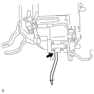
Install the No. 3 cooler unit drain hose.
88650N
8.INSTALL AIR CONDITIONING AMPLIFIER ASSEMBLY
Install the air conditioning amplifier assembly with the 2 screws.
Connect the connector.
88520
9.INSTALL COOLING BOX ASSEMBLY
Attach the 12 claws to install the cooling box assembly.
Install the 6 screws.
58860A
10.INSTALL CONSOLE BOX REGISTER ASSEMBLY
58907
11.INSTALL CONSOLE COMPARTMENT DOOR HINGE SUB-ASSEMBLY
Install the console compartment door hinge sub-assembly with the 4 screws.
Attach the 5 claws.
Install the 6 screws.
58905
12.INSTALL CONSOLE COMPARTMENT DOOR SUB-ASSEMBLY
Install the console compartment door sub-assembly with the 6 screws.