RM27T0E
_59
Vehicle Exterior
_053746
WIPER / WASHER
_0261257
WIPER AND WASHER SYSTEM
J
WIPER / WASHER WIPER AND WASHER SYSTEM Headlight Signal Circuit
DESCRIPTION
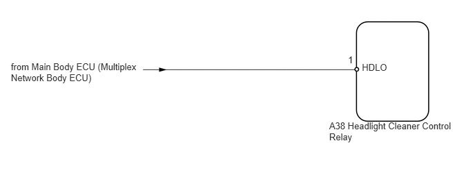
The headlight cleaner control relay detects the low beam headlights status.
WIRING DIAGRAM
5.461,0.939 5.905,1.099
0.443,0.160
10
HDLO
5.251,0.827 5.361,0.987
0.110,0.160
10
1
0.165,0.929 2.154,1.273
1.989,0.343
10
from Main Body ECU (Multiplex Network Body ECU)
4.967,1.822 7.001,2.169
2.034,0.347
10
A38 Headlight Cleaner Control Relay
CAUTION / NOTICE / HINT
- NOTICE:
-
First check that the low beam headlights operate normally.
PROCEDURE
1.CHECK HEADLIGHT CLEANER CONTROL RELAY (HDLO VOLTAGE)
a.
0.177,0.068 0.338,0.233
0.161,0.165
10
*a
1.967,1.698 2.427,1.850
0.460,0.151
10
HDLO
1.539,1.058 1.823,1.792
1.823,1.792 1.943,1.792
false
0.501,1.056 0.794,1.203
0.292,0.147
10
A38
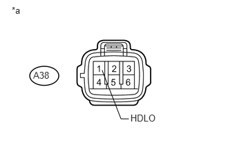
Disconnect the A38 headlight cleaner control relay connector.
b.
Measure the voltage according to the value(s) in the table below.
- Standard Voltage:
Tester Connection Switch Condition Specified Condition A38-1 (HDLO) - Body ground Headlight dimmer switch in head 11 to 14 V A38-1 (HDLO) - Body ground Headlight dimmer switch not in head Below 1 V
| *a | Front view of wire harness connector
(to Headlight Cleaner Control Relay) |
OK
PROCEED TO NEXT SUSPECTED AREA SHOWN IN PROBLEM SYMPTOMS TABLE
NG
REPAIR OR REPLACE HARNESS OR CONNECTOR