RM27T0E
_59
Vehicle Exterior
_053748
HORN
_0261296
INTEGRATION RELAY
G
HORN INTEGRATION RELAY ON-VEHICLE INSPECTION
PROCEDURE

 82662A
1.REMOVE NO. 1 RELAY BLOCK COVER
a.
Remove the No. 1 relay block cover.
82641
2.INSPECT NO. 1 INTEGRATION RELAY
a.
1.351,0.06 1.526,0.221
0.174,0.161
10
*1
2.043,0.06 2.217,0.221
0.174,0.161
10
*1
1.324,0.169 1.066,0.169
1.066,0.169 0.658,0.311
false
2.226,0.143 2.437,0.143
2.437,0.143 2.862,0.285
false
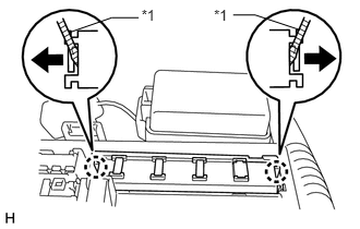
Using a screwdriver, detach the 2 claws and disconnect the No. 1 integration relay from the engine room junction block.
- HINT:
-
Tape the screwdriver tip before use.
| *1 | Protective Tape |
b.
2.394,0.498 2.593,0.651
0.199,0.152
10
1H
0.097,0.002 0.263,0.177
0.165,0.174
10
*a
2.809,0.149 2.974,0.323
0.165,0.174
10
*A
2.809,0.535 2.974,0.710
0.165,0.174
10
*B
2.397,0.146 2.596,0.299
0.199,0.152
10
1A
0.477,0.349 0.677,0.502
0.199,0.152
10
1C
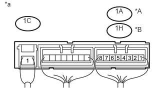
Measure the resistance according to the value(s) in the table below.
- Standard Resistance:
Tester Connection Condition Specified Condition 1A-8 - 1C-1 *A
1H-8 - 1C-1 *BBattery voltage is not applied to terminals 1C-1 and 1A-7 *A
Battery voltage is not applied to terminals 1C-1 and 1A-7*B10 kΩ or higher 1A-8 - 1C-1 *A
1H-8 - 1C-1 *BBattery voltage is applied to terminals 1C-1 and 1A-7 *A
Battery voltage is applied to terminals 1C-1 and 1A-7 *BBelow 1Ω
*A: for Gasoline Engine
*B: for Diesel Engine
If the result is not as specified, replace the No. 1 integration relay.
| *A | for Gasoline Engine |
| *B | for Diesel Engine |
| *a | Component with harness connected
(No. 1 Integration Relay) |
c.
Attach the 2 claws to install the No. 1 integration relay to the engine room junction block.
82662A
3.INSTALL NO. 1 RELAY BLOCK COVER
a.
Install the No. 1 relay block cover.