EXTERIOR PANELS / TRIM SIDE STEP REASSEMBLY
CAUTION / NOTICE / HINT
- HINT:
- ·
Use the same procedure for the RH and LH sides.
·The procedure listed below is for the LH side.
·A bolt without a torque specification is shown in the standard bolt chart (See page General>SPECIFICATIONS>STANDARD BOLT>SPECIFIED TORQUE FOR STANDARD BOLTS).
PROCEDURE

 81380D
1.INSTALL STEP LIGHT ASSEMBLY (w/ Illumination)
81399C
2.INSTALL STEP LIGHT BRACKET (w/ Illumination)
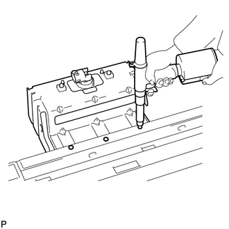
Install a nose piece to an air riveter or hand riveter.
Insert the mandrel part of a new rivet into the nose piece.
Using the riveter, install the step light bracket with the 3 rivets as shown in the illustration.
- HINT:
-
If the rivet cannot be cut, pull it once and cut it.
- NOTICE:
- ·
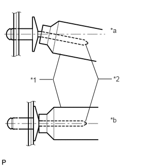 1.24,1.104 1.094,1.635 1.094,1.635 1.25,2.198 false 1.083,1.635 0.813,1.635 false 1.76,0.906 2.021,1.625 2.021,1.625 1.76,2.5 false 2.021,1.625 2.302,1.625 false 2.271,0.542 2.469,0.74 0.198,0.198 10 false *a 2.271,2.385 2.49,2.583 0.219,0.198 10 false *b 0.625,1.563 0.813,1.76 0.188,0.198 10 false *1 2.333,1.542 2.521,1.719 0.188,0.177 10 false *2
Do not pry the rivet with the riveter as this will cause damage to the riveter and mandrel.
Text in Illustration *1 Riveter *2 Mandrel *a INCORRECT *b CORRECT
·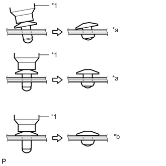 0.719,0.115 1.021,0.115 false 0.813,1.135 1.01,1.135 false 0.813,2.417 1.01,2.417 false 2.323,0.531 2.51,0.708 0.188,0.177 10 false *a 2.323,1.531 2.5,1.708 0.177,0.177 10 false *a 2.354,2.74 2.552,2.917 0.198,0.177 10 false *b 1.052,2.333 1.229,2.49 0.177,0.156 10 false *1 1.063,1.052 1.24,1.208 0.177,0.156 10 false *1 1.063,0.031 1.24,0.188 0.177,0.156 10 false *1
Confirm that the rivets are seated properly against the step light bracket.
·Do not tilt the riveter when installing the rivet to the step light bracket.
·Do not leave any space between the rivet head and step light bracket.
Text in Illustration *1 Riveter *a INCORRECT *b CORRECT
·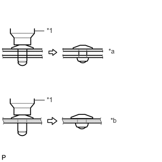 0.74,0.656 0.938,0.656 false 0.74,2.125 0.948,2.125 false 2.302,1 2.5,1.177 0.198,0.177 10 false *a 2.344,2.469 2.552,2.646 0.208,0.177 10 false *b 0.99,0.563 1.188,0.729 0.198,0.167 10 false *1 0.99,2.031 1.198,2.198 0.208,0.167 10 false *1
Do not leave any space between the step light bracket and step plate. Firmly hold together the 2 items while installing the rivet.
Text in Illustration *1 Riveter *a INCORRECT *b CORRECT
81380D
3.INSTALL STEP LIGHT ASSEMBLY (w/ Illumination)
82158
4.INSTALL STEP PANEL WIRE LH (w/ Illumination)
51077B
5.INSTALL SIDE STEP BRACKET SUB-ASSEMBLY LH
Install a nose piece to an air riveter or hand riveter.
Insert the mandrel part of a new rivet into the nose piece.
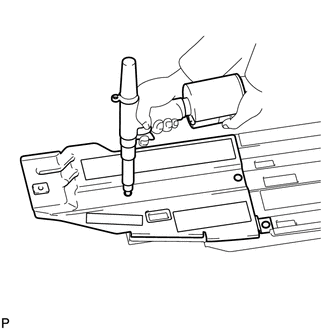
Using the riveter, install the side step bracket with 3 rivets as shown in the illustration.
- HINT:
-
If the rivet cannot be cut, pull it once and cut it.
- NOTICE:
- ·
1.24,1.104 1.094,1.635 1.094,1.635 1.25,2.198 false 1.083,1.635 0.813,1.635 false 1.76,0.906 2.021,1.625 2.021,1.625 1.76,2.5 false 2.021,1.625 2.302,1.625 false 2.271,0.542 2.469,0.74 0.198,0.198 10 false *a 2.271,2.385 2.49,2.583 0.219,0.198 10 false *b 0.625,1.563 0.813,1.76 0.188,0.198 10 false *1 2.333,1.542 2.521,1.719 0.188,0.177 10 false *2
Do not pry the rivet with the riveter as this will cause damage to the riveter and mandrel.
Text in Illustration *1 Riveter *2 Mandrel *a INCORRECT *b CORRECT
·
0.719,0.115 1.021,0.115 false 0.813,1.135 1.01,1.135 false 0.813,2.417 1.01,2.417 false 2.323,0.531 2.51,0.708 0.188,0.177 10 false *a 2.323,1.531 2.5,1.708 0.177,0.177 10 false *a 2.354,2.74 2.552,2.917 0.198,0.177 10 false *b 1.052,2.333 1.229,2.49 0.177,0.156 10 false *1 1.063,1.052 1.24,1.208 0.177,0.156 10 false *1 1.063,0.031 1.24,0.188 0.177,0.156 10 false *1
Confirm that the rivets are seated properly against the side step bracket.
·Do not tilt the riveter when installing the rivet to the side step bracket.
·Do not leave any space between the rivet head and side step bracket.
Text in Illustration *1 Riveter *a INCORRECT *b CORRECT
·
0.74,0.656 0.938,0.656 false 0.74,2.125 0.948,2.125 false 2.302,1 2.5,1.177 0.198,0.177 10 false *a 2.344,2.469 2.552,2.646 0.208,0.177 10 false *b 0.99,0.563 1.188,0.729 0.198,0.167 10 false *1 0.99,2.031 1.198,2.198 0.208,0.167 10 false *1
Do not leave any space between the side step bracket and step plate. Firmly hold together the 2 items while installing the rivet.
Text in Illustration *1 Riveter *a INCORRECT *b CORRECT
51779B
6.INSTALL NO. 2 SIDE STEP PLATE COVER
Install the No. 2 side step plate cover.
51774C
7.INSTALL STEP PLATE COVER LH
Install the side step plate cover.
51772D
8.INSTALL STEP PLATE LH (for 5 Door)
Attach the 17 claws to install the step plate.
Install the 3 bolts and clip.
- Torque:
- 2.3 N*m (24 kgf*cm, 20 in.*lbf)
51772D
9.INSTALL STEP PLATE LH (for 3 Door)
Attach the 14 claws to install the step plate.
Install the 3 bolts and clip.
- Torque:
- 2.3 N*m (24 kgf*cm, 20 in.*lbf)
75862C
10.INSTALL NO. 2 ROCKER PANEL MOULDING PROTECTOR
Install the No. 2 rocker panel moulding protector with the 2 bolts.
- Torque:
- 3.0 N*m (31 kgf*cm, 27 in.*lbf)
51798
11.INSTALL NO. 3 SIDE STEP BRACKET LH
Install the No. 3 side step bracket with the 2 bolts.
- Torque:
- 6.0 N*m (61 kgf*cm, 53 in.*lbf)
51796
12.INSTALL NO. 2 SIDE STEP BRACKET LH
Install the No. 2 side step bracket with the 2 bolts.
- Torque:
- 6.0 N*m (61 kgf*cm, 53 in.*lbf)
51793B
13.INSTALL SIDE STEP BRACKET LH
Install the side step bracket with the 2 bolts.
- Torque:
- 6.0 N*m (61 kgf*cm, 53 in.*lbf)