SLIDING ROOF / CONVERTIBLE SLIDING ROOF SYSTEM Sliding Roof ECU Power Source Circuit
DESCRIPTION
If the sliding function and tilt function do not operate, there may be a malfunction in the sliding roof drive gear sub-assembly power source circuit.
WIRING DIAGRAM
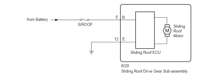
CAUTION / NOTICE / HINT
- NOTICE:
- ·
When the sliding roof drive gear sub-assembly is removed and reinstalled or replaced, the sliding roof drive gear sub-assembly must be initialized (See page Vehicle Exterior>SLIDING ROOF / CONVERTIBLE>SLIDING ROOF SYSTEM>INITIALIZATION).
·Inspect the fuses for circuits related to this system before performing the following inspection procedure.
PROCEDURE
Use the Data List to check if the ignition switch signal is functioning properly (See pageVehicle Exterior>SLIDING ROOF / CONVERTIBLE>SLIDING ROOF SYSTEM>DATA LIST / ACTIVE TEST).
| Tester Display | Measurement Item/Range | Normal Condition | Diagnostic Note |
|---|---|---|---|
| Ignition (Direct Signal) | Ignition switch signal / ON or OFF | ON: Ignition switch ON
OFF: Ignition switch off |
- |
| Ignition (MPX) | Ignition switch signal (LIN signal) / ON or OFF | ON: Ignition switch ON
OFF: Ignition switch off |
- |
- OK:
The intelligent tester displays as shown in the table according to the operation of each switch.
OK
NG
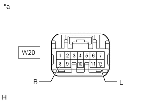
Disconnect the W20 ECU connector.
Measure the resistance and voltage according to the value(s) in the table below.
- Standard Resistance:
Tester Connection Condition Specified Condition W20-12 (E) - Body ground Always Below 1 Ω
- Standard Voltage:
Tester Connection Condition Specified Condition W20-8 (B) - Body ground Always 11 to 14 V
| *a | Front view of wire harness connector
(to Sliding Roof Drive Gear Sub-assembly) |
OK
NG