BRAKE CONTROL / DYNAMIC CONTROL SYSTEMS FRONT SPEED SENSOR REMOVAL
CAUTION / NOTICE / HINT
- HINT:
- ·
The procedure listed below is for the LH side.
·Other than areas where instructions are provided, use the same procedures for the RH and LH sides.
PROCEDURE

 42603
1.REMOVE FRONT WHEEL
89516
2.REMOVE SKID CONTROL SENSOR WIRE (except 1GD-FTV)
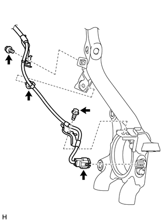
Disconnect the connector from the front speed sensor LH.
Remove the 2 bolts and 2 harness clamps.
Detach the clip.
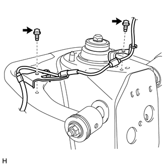
Remove the 2 bolts and 2 harness clamps.
Disconnect the connector as follows.
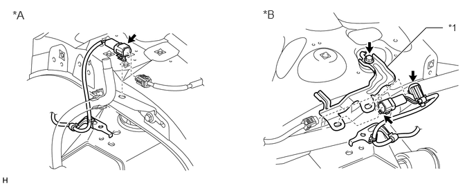
| *A | for LH | *B | for RH |
| *1 | NO. 3 SKID CONTROL SENSOR CLAMP | - | - |
for LH:
Disconnect the connector.
Detach the connector.
for RH:
Disconnect the connector.
Detach the connector from the No. 3 skid control sensor clamp.
Detach the clip.
Remove the bolt and No. 3 skid control sensor clamp.
89516
3.REMOVE SKID CONTROL SENSOR WIRE (for 1GD-FTV)
Disconnect the connector from the front speed sensor LH.
Remove the 2 bolts and 2 harness clamps.
Detach the clip.
Remove the 2 bolts and 2 harness clamps.
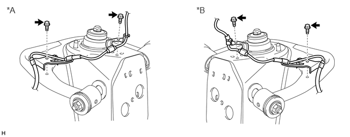
| *A | for LH | *B | for RH |
Disconnect the connector as follows.
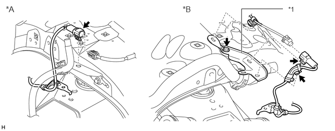
| *A | for LH | *B | for RH |
| *1 | NO. 3 SKID CONTROL SENSOR CLAMP | - | - |
for LH:
Disconnect the connector.
Detach the connector.
for RH:
Disconnect the connector.
Detach the connector from the No. 3 skid control sensor clamp.
Detach the 2 clips.
Remove the bolt and No. 3 skid control sensor clamp.
4.REMOVE SKID CONTROL SENSOR CLAMP
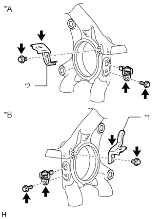
| *A | for LH |
| *B | for RH |
| *1 | No. 1 Skid Control Sensor Clamp |
| *2 | No. 2 Skid Control Sensor Clamp |
for LH:
Remove the bolt and No. 2 skid control sensor clamp from the knuckle.
for RH:
Remove the bolt and No. 1 skid control sensor clamp from the knuckle.
89543
5.REMOVE FRONT SPEED SENSOR LH
Remove the bolt and front speed sensor LH from the knuckle.
- NOTICE:
-
Pull out the sensor while trying as much as possible not to rotate it.
89542
6.REMOVE FRONT SPEED SENSOR RH
- HINT:
-
Use the same procedure described for the LH side.