RM27T0E
_57
Power Source / Network
_053729
NETWORKING
_0325854
CAN COMMUNICATION SYSTEM(w/ Central Gateway ECU)
U
NETWORKING CAN COMMUNICATION SYSTEM(w/ Central Gateway ECU) SYSTEM DIAGRAM
SYSTEM DIAGRAM
a.
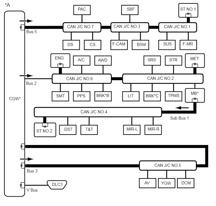
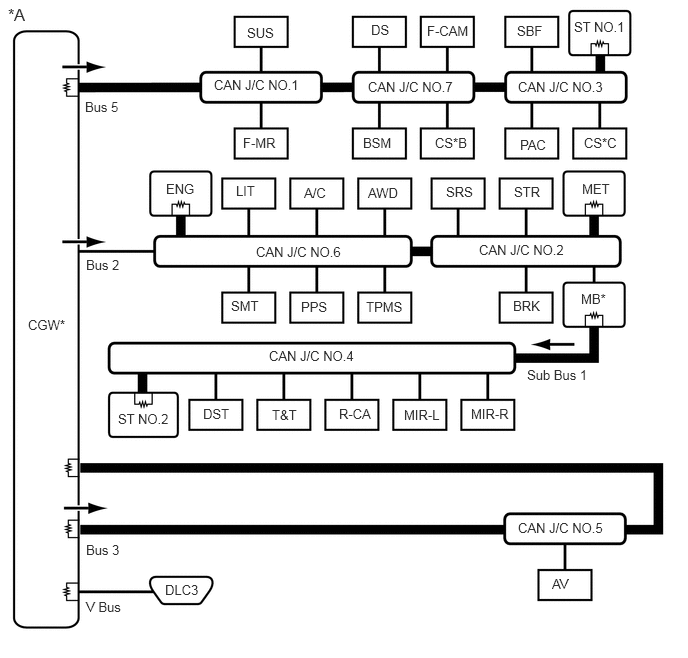
The CAN communication system is composed of 5 buses.
0.156,0.063 0.531,0.302
0.375,0.24
12
false
*A
0.875,0.969 1.25,1.208
0.375,0.24
10
false
Bus 5
0.865,2.688 1.406,2.938
0.542,0.25
10
false
Bus 2
0.896,5.604 1.458,5.844
0.563,0.24
10
false
Bus 3
0.885,6.24 1.51,6.542
0.625,0.302
10
false
V Bus
2.583,0.219 2.958,0.458
0.375,0.24
10
false
PAC
2.979,1.396 3.354,1.635
0.375,0.24
10
false
CS
2.24,1.396 2.615,1.635
0.375,0.24
10
false
DS
3.729,1.375 4.271,1.677
0.542,0.302
10
false
F-CAM
4.542,1.396 4.917,1.635
0.375,0.24
10
false
BSM
4.208,0.219 4.583,0.458
0.375,0.24
10
false
SBF
5.979,0.219 6.604,0.417
0.625,0.198
10
false
ST NO.1
2.229,0.802 3.229,0.99
1,0.188
10
false
CAN J/C NO.7
5.417,1.375 5.792,1.615
0.375,0.24
10
false
SUS
6.063,1.375 6.51,1.625
0.448,0.25
10
false
F-MR
6.313,1.865 6.688,2.104
0.375,0.24
10
false
MET
5.615,1.906 5.99,2.146
0.375,0.24
10
false
STR
4.896,1.906 5.271,2.146
0.375,0.24
10
false
SRS
3.25,1.917 3.625,2.156
0.375,0.24
10
false
AWD
2.583,1.906 2.958,2.146
0.375,0.24
10
false
A/C
1.823,1.844 2.198,2.083
0.375,0.24
10
false
ENG
1.865,3.104 2.24,3.344
0.375,0.24
10
false
SMT
2.563,3.104 2.938,3.344
0.375,0.24
10
false
PPS
3.198,3.094 3.74,3.333
0.542,0.24
10
false
BRK*B
4.24,3.104 4.615,3.344
0.375,0.24
10
false
LIT
4.833,3.104 5.344,3.333
0.51,0.229
10
false
BRK*C
5.573,3.094 6.073,3.375
0.5,0.281
10
false
TPMS
6.333,3.021 6.708,3.26
0.375,0.24
10
false
MB*
4.896,4.208 5.375,4.448
0.479,0.24
10
false
MIR-R
4.198,4.208 4.646,4.469
0.448,0.26
10
false
MIR-L
2.833,4.219 3.208,4.458
0.375,0.24
10
false
T&T
2.135,4.219 2.51,4.458
0.375,0.24
10
false
DST
1.208,4.271 1.854,4.542
0.646,0.271
10
false
ST NO.2
1.729,6.052 2.219,6.302
0.49,0.25
10
false
DLC3
4.792,6 5.167,6.24
0.375,0.24
10
false
AV
5.354,6.01 5.781,6.271
0.427,0.26
10
false
YGW
6.021,6 6.396,6.24
0.375,0.24
10
false
DCM
0.302,3.198 0.844,3.448
0.542,0.25
10
false
CGW*
3.771,0.792 4.771,0.979
1,0.188
10
false
CAN J/C NO.3
5.438,0.802 6.438,0.99
1,0.188
10
false
CAN J/C NO.1
2.198,2.531 3.198,2.719
1,0.188
10
false
CAN J/C NO.6
4.885,2.521 5.885,2.708
1,0.188
10
false
CAN J/C NO.2
2.677,3.635 3.677,3.823
1,0.188
10
false
CAN J/C NO.4
5.646,3.844 6.427,4.115
0.781,0.271
10
false
Sub Bus 1
5.125,5.417 6.125,5.604
1,0.188
10
false
CAN J/C NO.5
| *A | for LHD | *B | for 2TR-FE |
| *C | except 2TR-FE | - | - |

|
CAN Main Bus Line | 
|
Terminating Resistor |

|
CAN Branch Line | * | Gateway Function Equipped ECU |

|
Bus Monitoring Direction | - | - |
0.083,0.052 0.458,0.292
0.375,0.24
12
false
*A
0.292,3.302 0.844,3.542
0.552,0.24
10
false
CGW*
2.229,0.802 3.375,1
1.146,0.198
10
false
CAN J/C NO.1
3.833,0.823 4.979,1.021
1.146,0.198
10
false
CAN J/C NO.7
5.396,0.823 6.542,1.021
1.146,0.198
10
false
CAN J/C NO.3
4.99,2.521 6.135,2.719
1.146,0.198
10
false
CAN J/C NO.2
2.667,2.542 3.813,2.74
1.146,0.198
10
false
CAN J/C NO.6
2.802,3.625 3.948,3.823
1.146,0.198
10
false
CAN J/C NO.4
5.396,5.417 6.542,5.615
1.146,0.198
10
false
CAN J/C NO.5
2.573,0.26 3.125,0.5
0.552,0.24
10
false
SUS
3.865,0.229 4.417,0.469
0.552,0.24
10
false
DS
4.448,0.24 5,0.479
0.552,0.24
10
false
F-CAM
5.385,0.24 5.938,0.479
0.552,0.24
10
false
SBF
5.979,0.198 6.75,0.458
0.771,0.26
10
false
ST NO.1
2.531,1.406 3.083,1.646
0.552,0.24
10
false
F-MR
2.458,1.906 3.01,2.146
0.552,0.24
10
false
LIT
3.781,1.406 4.333,1.646
0.552,0.24
10
false
BSM
4.531,1.406 5.083,1.646
0.552,0.24
10
false
CS*B
6.063,1.885 6.615,2.125
0.552,0.24
10
false
MET
6.083,1.406 6.635,1.646
0.552,0.24
10
false
CS*C
5.417,1.427 5.969,1.667
0.552,0.24
10
false
PAC
5.354,1.917 5.906,2.156
0.552,0.24
10
false
STR
4.646,1.917 5.198,2.156
0.552,0.24
10
false
SRS
5.344,3.104 5.896,3.344
0.552,0.24
10
false
BRK
6.052,3.031 6.604,3.271
0.552,0.24
10
false
MB*
2.406,3.104 2.958,3.344
0.552,0.24
10
false
SMT
3.135,3.115 3.688,3.354
0.552,0.24
10
false
PPS
3.813,3.115 4.365,3.354
0.552,0.24
10
false
TPMS
1.729,1.885 2.281,2.125
0.552,0.24
10
false
ENG
3.167,1.927 3.719,2.167
0.552,0.24
10
false
A/C
3.833,1.927 4.385,2.167
0.552,0.24
10
false
AWD
1.229,4.281 2,4.542
0.771,0.26
10
false
ST NO.2
2.115,4.229 2.667,4.469
0.552,0.24
10
false
DST
2.833,4.24 3.385,4.479
0.552,0.24
10
false
T&T
3.531,4.229 4.083,4.469
0.552,0.24
10
false
R-CA
4.208,4.24 4.76,4.479
0.552,0.24
10
false
MIR-L
4.906,4.229 5.458,4.469
0.552,0.24
10
false
MIR-R
5.75,6 6.302,6.24
0.552,0.24
10
false
AV
1.719,6.063 2.271,6.302
0.552,0.24
10
false
DLC3
0.885,1.031 1.438,1.271
0.552,0.24
10
false
Bus 5
0.896,2.677 1.448,2.917
0.552,0.24
10
false
Bus 2
0.896,5.646 1.448,5.885
0.552,0.24
10
false
Bus 3
5.49,3.823 6.271,4.073
0.781,0.25
10
false
Sub Bus 1
0.896,6.24 1.448,6.479
0.552,0.24
10
false
V Bus
| *A | for RHD | *B | for 8 Sensor Type |
| *C | for 4 Sensor Type | - | - |
|
|
CAN Main Bus Line |
|
Terminating Resistor |
|
|
CAN Branch Line | * | Gateway Function Equipped ECU |
|
|
Bus Monitoring Direction | - | - |
| Connected to | Code | ECU/Sensor Name | CAN DTC Storage | Note |
|---|---|---|---|---|
| - | CGW | Central Gateway ECU (Network Gateway ECU) | - | - |
| V Bus | DLC3 | DLC3 | - | - |
| Bus 2 | ENG | ECM | Available | - |
| A/C | Air Conditioning Amplifier Assembly | Available | - | |
| AWD | 4 Wheel Drive Control ECU (4WD Control ECU) | Available | - | |
| SMT | Certification ECU (Smart Key ECU Assembly) | Available | w/ Entry and Start System | |
| PPS | Power Steering ECU Assembly | Available | - | |
| BRK | Master Cylinder Solenoid (Skid Control ECU) | Available | except 2TR-FE | |
| Brake Actuator Assembly (Skid Control ECU) | Available | for 2TR-FE | ||
| SRS | Airbag Sensor Assembly | - | - | |
| STR | Steering Sensor | - | - | |
| MET | Combination Meter Assembly | Available | - | |
| TPMS | Tire Pressure Warning ECU and Receiver | Available | w/ Tire Pressure Warning System | |
| LIT | No. 1 Headlight ECU Sub-assembly LH | Available | for LED Headlight | |
| MB | Main Body ECU (Multiplex Network Body ECU) | Available | ·
The main body ECU (multiplex network body ECU) functions as a gateway between the bus 2 and sub bus 1 ·
Connected to LIN communication system |
|
| CAN J/C NO.2 | No. 2 CAN Junction Connector | - | - | |
| CAN J/C NO.6 | No. 6 CAN Junction Connector | - | - | |
| Bus 3 | AV | Navigation Receiver Assembly (EMVN ECU) | Available | w/ Navigation System |
| Radio and Display Receiver Assembly (EMVN ECU) | Available | w/ Audio and Visual System | ||
| DCM | Telematics transceiver | Available | w/ Telematics Transceiver | |
| YGW | Bus Buffer ECU | - | w/ Bus Buffer ECU | |
| CAN J/C NO. 5 | No. 5 CAN Junction Connector | - | - | |
| Bus 5 | PAC | Parking Assist ECU | Available | w/ Parking Assist Monitor System (w/ Multi-display) |
| DS | Driving Support ECU Assembly | Available | w/ Pre-crash Safety System | |
| CS | Clearance Warning ECU Assembly | Available | w/ TOYOTA Parking Assist-sensor System | |
| SBF | Stabilizer Control ECU | Available | w/ Kinetic Dynamic Suspension System | |
| F-CAM | Forward Recognition Camera | Available | w/ Pre-crash Safety System | |
| BSM | Blind Spot Monitor Sensor LH | Available | w/ Blind Spot Monitor System | |
| F-MR | Millimeter Wave Radar Sensor Assembly | - | w/ Pre-crash Safety System | |
| SUS | Suspension Control ECU | Available | w/ Air Suspension System | |
| ST NO.1 | No .1 CAN Junction Terminal | - | - | |
| CAN J/C NO.1 | No. 1 CAN Junction Connector | - | - | |
| CAN J/C No.3 | No. 3 CAN Junction Connector | - | - | |
| CAN J/C No.7 | No. 7 CAN Junction Connector | - | - | |
| Sub Bus 1 | MB | Main Body ECU (Multiplex Network Body ECU) | Available | ·
The main body ECU (multiplex network body ECU) functions as a gateway between the bus 2 and sub bus 1 ·
Connected to LIN communication system |
| DST | Front Power Seat Switch (Power Seat Control ECU) | - | w/ Seat Memory | |
| MIR-L | Outer Mirror Control ECU Assembly LH | Available | w/ Reverse Shift-linked Mirror | |
| MIR-R | Outer Mirror Control ECU Assembly RH | Available | w/ Reverse Shift-linked Mirror | |
| T&T | Multiplex Tilt and Telescopic ECU | Available | for Power Tilt and Power Telescopic Steering Column | |
| R-CA | Rear Television Camera Assembly | Available | w/ Rear Television Camera Assembly (built-in ECU) | |
| CAN J/C NO. 4 | No. 4 CAN Junction Connector | - | - | |
| ST NO. 2 | No. 2 CAN Junction Terminal | - | - |