INTERIOR PANELS / TRIM FRONT CONSOLE BOX(for Automatic Transmission) INSTALLATION
CAUTION / NOTICE / HINT
- HINT:
- ·
Use the same procedure for RHD and LHD vehicles.
·The procedure listed below is for LHD vehicles.
·A bolt without a torque specification is shown in the standard bolt chart.
Click hereGeneral>SPECIFICATIONS>STANDARD BOLT>SPECIFIED TORQUE FOR STANDARD BOLTS
PROCEDURE

 58910C
1.INSTALL REAR CONSOLE BOX ASSEMBLY
Connect each connector.
Install the rear console box assembly with the 2 screws, clip and 5 bolts.
58903A
2.INSTALL REAR CONSOLE END PANEL SUB-ASSEMBLY
Connect each connector.
Attach the 4 clips and 4 claws to install the rear console end panel sub-assembly.
58861B
3.INSTALL NO. 1 CONSOLE BOX DUCT (for Single Air Conditioning System)
Install the No. 1 console box duct with the clip.
55084E
4.INSTALL NO. 1 HEATER TO REGISTER DUCT SUB-ASSEMBLY (w/ Cool Box)
Attach the 4 claws to install the No. 1 heater to register duct sub-assembly.
Attach the 2 clamps.
5.INSTALL CONSOLE PANEL SUB-ASSEMBLY
Connect each connector.
Attach the 8 clips and 2 claws to install the console panel sub-assembly.
33504F
6.INSTALL SHIFT LEVER KNOB SUB-ASSEMBLY
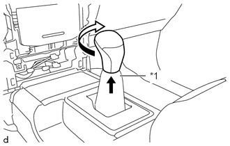
| *1 | Shifting Hole Cover |
Install the shift lever knob sub-assembly and twist it in the direction indicated by the arrow.
Install the shifting hole cover to the shift lever knob sub-assembly.
58817A
7.INSTALL FRONT NO. 2 CONSOLE BOX INSERT
Attach the 2 clips and guide to install the front No. 2 console box insert.
55607
8.INSTALL NO. 2 INSTRUMENT PANEL UNDER COVER SUB-ASSEMBLY
Attach the 3 clips and 2 guides to install the No. 2 instrument panel under cover sub-assembly.
Install the screw.
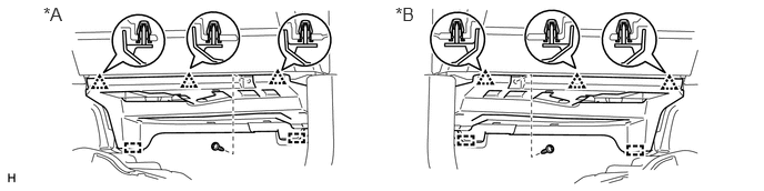
| *A | for LHD | *B | for RHD |
58816B
9.INSTALL CONSOLE BOX INSERT
Attach the 2 clips and guide to install the console box insert.
55606
10.INSTALL NO. 1 INSTRUMENT PANEL UNDER COVER SUB-ASSEMBLY
for LHD:
Attach the 2 clips and 2 guides to install the No. 1 instrument panel under cover sub-assembly.
Install the screw.
for RHD:
Attach the 3 clips and 2 guides to install the No. 1 instrument panel under cover sub-assembly.
Install the screw.
58805E
11.INSTALL LOWER CONSOLE PANEL SUB-ASSEMBLY (w/o Module Switch)
w/ Combination Switch:
Connect each connector.
Attach the 10 clips to install the lower console panel sub-assembly.
w/o Combination Switch:
Connect each connector.
Attach the 10 clips to install the lower console panel sub-assembly.
55405B
12.INSTALL CENTER INSTRUMENT CLUSTER FINISH PANEL SUB-ASSEMBLY (w/ Module Switch)
Attach the 4 clips to install the center instrument cluster finish panel sub-assembly.
55449C
13.INSTALL NO. 2 INSTRUMENT PANEL FINISH PANEL CUSHION
Attach the 5 clips to install the No. 2 instrument panel finish panel cushion.
55436A
14.INSTALL INSTRUMENT PANEL FINISH PANEL END LH
w/ Entry and Start System:
Connect the connector.
Attach the 5 clips to install the instrument panel finish panel end LH.
55448A
15.INSTALL NO. 1 INSTRUMENT PANEL FINISH PANEL CUSHION
- HINT:
-
Use the same procedure described for the No. 2 instrument panel finish panel cushion.
55435A
16.INSTALL INSTRUMENT PANEL FINISH PANEL END RH
w/ Airbag Cut Off Switch:
Connect the connector.
Attach the 5 clips to install the instrument panel finish panel end RH.
84010A
17.INSTALL INTEGRATION CONTROL AND PANEL ASSEMBLY