RM27T0E
_55
Steering
_053718
STEERING COLUMN
_0260965
STEERING HEATER SWITCH
G
STEERING COLUMN STEERING HEATER SWITCH INSPECTION
PROCEDURE

 84255
1.INSPECT STEERING HEATER SWITCH
a.
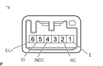
2.917,1.781 2.417,1.375
true
2.333,1.865 2.115,1.385
true
1.25,1.896 1.573,1.385
true
0.813,1.865 1.26,1.375
true
0.438,1.615 1.021,1.375
true
0.198,0.156 0.708,0.49
0.51,0.333
10
false
*a
2.344,1.917 2.708,2.115
0.365,0.198
10
false
RC
2.969,1.74 3.333,1.938
0.365,0.198
10
false
E
1.146,1.906 1.646,2.125
0.5,0.219
10
false
INDC
0.688,1.896 1.052,2.094
0.365,0.198
10
false
IG
0.167,1.583 0.531,1.781
0.365,0.198
10
false
ILL+
| *a | Component without harness connected
(Steering Heater Switch) |
Measure the voltage according to the value (s) in the table below.
- Standard Voltage:
Tester Connection (Positive (+) Tester Probe - Negative (-) Tester Probe) Switch Condition Specified Condition 5 (IG) - 4 (INDC) Always Below 1.25 V 2 (RC) - 4 (INDC) Steering heater switch is pushed Below 1.25 V
- HINT:
-
As the circuit has a diode, perform the measurement in diode test mode, and do not mistake the polarity.
b.
Measure the resistance according to the value(s) in the table below.
- Standard Resistance:
Tester Connection Switch Condition Specified Condition 5 (IG) - 2 (RC) Pressed Below 1 Ω Not pressed 10 kΩ or higher
If the result is not as specified, replace the steering heater switch.
c.
Check the illumination.
i.
Apply battery voltage between the terminals of the switch, and check the illumination condition of the steering heater switch.
- Standard Resistance:
Measurement Condition Specified Condition Battery positive (+) → A6 (ILL+) Battery negative (-) → A1 (E) Illuminates