RM27T0E
_56
Audio / Visual / Telematics
_053720
AUDIO / VIDEO
_0260969
AUDIO AND VISUAL SYSTEM(for Radio and Display Type)
U
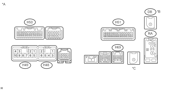
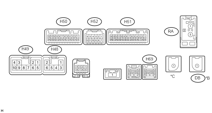
AUDIO / VIDEO AUDIO AND VISUAL SYSTEM(for Radio and Display Type) TERMINALS OF ECU
CHECK RADIO AND DISPLAY RECEIVER ASSEMBLY
4.875,1.917 5.333,2.115
0.458,0.198
10
false
H69
1.135,0.854 1.594,1.052
0.458,0.198
10
false
H50
0.948,2.667 1.406,2.865
0.458,0.198
10
false
H49
1.833,2.667 2.292,2.865
0.458,0.198
10
false
H48
4.885,0.854 5.344,1.052
0.458,0.198
10
false
H51
6.26,0.417 6.719,0.615
0.458,0.198
10
false
DB
6.656,0.406 7.115,0.604
0.458,0.198
10
false
*B
6.281,1.333 6.74,1.531
0.458,0.198
10
false
RA
0.083,0.094 0.542,0.292
0.458,0.198
10
false
*A
5.604,2.813 6.063,3.01
0.458,0.198
10
false
*C
| *A | for 6 Speakers | *B | w/ DAB Function |
| *C | w/ Navigation Antenna | - | - |
0.729,1.563 1.188,1.76
0.458,0.198
10
false
H49
1.719,1.573 2.177,1.771
0.458,0.198
10
false
H48
2.021,0.635 2.479,0.833
0.458,0.198
10
false
H50
3.063,0.635 3.521,0.833
0.458,0.198
10
false
H52
4.927,1.906 5.385,2.104
0.458,0.198
10
false
H69
5.677,0.969 6.135,1.167
0.458,0.198
10
false
RA
6.583,2.542 7.042,2.74
0.458,0.198
10
false
DB
6.948,2.552 7.156,2.771
0.208,0.219
10
false
*B
5.76,2.49 5.969,2.708
0.208,0.219
10
false
*C
4.198,0.646 4.656,0.844
0.458,0.198
10
false
H51
| *A | for 9 Speakers | *B | w/ DAB Function |
| *C | w/ Navigation Antenna | - | - |
| Terminal No. (Symbol) | Wiring Color | Terminal Description | Condition | Specified Condition |
|---|---|---|---|---|
| H48-1 (RR+) - H49-7 (GND1)*1 | R - BR | Voice signal | Voice guidance sounding | A waveform synchronized with voice signals is output |
| H48-2 (RL+) - H49-7 (GND1) | B - BR | Voice signal | Voice guidance sounding | A waveform synchronized with voice signals is output |
| H48-3 (RR-) - H49-7 (GND1)*1 | W - BR | Voice signal | Voice guidance sounding | A waveform synchronized with voice signals is output |
| H48-6 (RL-) - H49-7 (GND1) | Y - BR*1
W - BR*2 |
Voice signal | Voice guidance sounding | A waveform synchronized with voice signals is output |
| H49-1 (FR+) - H49-7 (GND1) | LG - BR*1
G - BR*2 |
Sound signal (Right) | Audio system playing | A waveform synchronized with sound signals is output |
| H49-2 (FL+) - H49-7 (GND1) | P - BR*1
B - BR*2 |
Sound signal (Left) | Audio system playing | A waveform synchronized with sound signals is output |
| H49-3 (ACC1) - H49-7 (GND1) | GR - BR | Power source (ACC) | Ignition switch ACC | 11 to 14 V |
| Ignition switch off | Below 1 V | |||
| H49-4 (+B1) - H49-7 (GND1) | R - BR | Power source | Always | 11 to 14 V |
| H49-5 (FR-) - H49-7 (GND1) | L - BR*1
R - BR*2 |
Sound signal (Right) | Audio system playing | A waveform synchronized with sound signals is output |
| H49-6 (FL-) - H49-7 (GND1) | V - BR*1
W - BR*2 |
Sound signal (Left) | Audio system playing | A waveform synchronized with sound signals is output |
| H49-7 (GND1) - Body ground | BR - Body ground | Ground | Always | Below 1 Ω |
| H49-10 (ILL+) - H49-7 (GND1) | G - BR | Illumination signal | Ignition switch ON, light control switch off → tail or head position | Below 1 V → 11 to 14 V |
| H50-3 (CNH1) | G | Local bus communication signal | - | - |
| H50-4 (CNL1) | W | Local bus communication signal | - | - |
| H50-7 (TX3+)*5 | L | AVC-LAN communication signal | - | - |
| H50-8 (TX3-)*5 | LG | AVC-LAN communication signal | - | - |
| H51-1 (IG) - H49-7 (GND1) | L - BR | Power source (IG) | Ignition switch ON | 11 to 14 V |
| Ignition switch off | Below 1 V | |||
| H51-2 (REV) - H49-7 (GND1) | R - BR | Reverse signal | See "Vehicle Signal Check Mode" in Operation Check (See page ( )) |
- |
| H51-4 (MACC) - H49-7 (GND1)*6 | R - BR | Telephone microphone assembly power supply | Ignition switch off | Below 1 V |
| Ignition switch ACC | 4 to 6 V | |||
| H51-5 (MIN+) - H49-7 (GND1) | B - BR | Microphone voice signal | See "Microphone & Voice Recognition Check" in Operation Check (See page ())
|
- |
| H51-6 (SNS2) - H49-7 (GND1) | GR - BR | Telephone microphone assembly detection signal ground | Always | Below 1 Ω |
| H51-7 (TX1+)*2 | B | AVC-LAN communication signal | - | - |
| H51-8 (TX1-)*2 | W | AVC-LAN communication signal | - | - |
| H51-9 (CANH) | R | CAN communication signal | - | - |
| H51-10 (CANL) | W | CAN communication signal | - | - |
| H51-11 (AGND) - Body ground | Shielded - Body ground | Shield ground | Always | Below 1 Ω |
| H51-15 (PKB) - H49-7 (GND1) | LG -BR | Parking brake switch signal | See "Vehicle Signal Check Mode" in Operation Check (See page ())
|
- |
| H51-16 (MUT1) - H49-7 (GND1)*2 | GR - BR | Mute signal | Ignition switch ACC, audio system playing | 2.0 V or higher |
| Audio system changing modes | Below 1 V | |||
| H51-17 (SPD) - H49-7 (GND1) | R - BR | Speed signal from combination meter assembly | See "Vehicle Signal Check Mode" in Operation Check (See page ())
|
- |
| H51-18 (SGND) - H49-7 (GND1) | Shielded - BR | Shield ground | Always | Below 1 Ω |
| H51-19 (MIN-) - Body ground | W - Body ground | Microphone voice signal | See "Microphone & Voice Recognition Check" in Operation Check (See page ())
|
- |
| H51-21 (SW1) - H51-23 (SWG) | W - W-B | Steering pad switch signal | Steering pad switch not operated | 4.44 to 5.43 V |
| Seek+ switch pushed | 0.45 to 0.65 V | |||
| Seek- switch pushed | 1.19 to 1.49 V | |||
| Vol+ switch pushed | 2.09 to 2.54 V | |||
| Vol- switch pushed | 3.2 to 3.88 V | |||
| H51-22 (SW2) - H51-23 (SWG) | B - W-B | Steering pad switch signal | Steering pad switch not operated | 4.44 to 5.43 V |
| MODE switch pushed | 0.45 to 0.65 V | |||
| On hook switch pushed | 1.19 to 1.49 V | |||
| Off hook switch pushed | 2.09 to 2.54 V | |||
| Voice switch pushed | 3.2 to 3.88 V | |||
| H51-23 (SWG) - Body ground | W-B - Body ground | Steering pad switch ground | Always | Below 1 Ω |
| H51-25 (ADPG) - H49-7 (GND1) | L - BR | External device connector detection signal | External device connected | Below 1 V |
| External device not connected | 2.7 to 3.4 V | |||
| H51-26 (VAR+) - H51-27 (VA-) | R - B | Sound signal (Right) | AUX audio device playing (When stereo jack adapter used) | A waveform synchronized with voice signals is output |
| H51-27 (VA-) - H49-7 (GND1) | B - BR | Sound signal ground | Always | Below 1 Ω |
| H51-28 (VAL+) - H51-27 (VA-) | W - B | Sound signal (Left) | AUX audio device playing (When stereo jack adapter used) | A waveform synchronized with voice signals is output |
| H52-8 (MUTE) - H49-7 (GND1)*2, *3 | R - BR | Mute signal | Ignition switch ACC, audio system playing | 2.0 V or higher |
| Audio system changing modes | Below 1 V | |||
| H52-2 (CDR+) - H49-7 (GND1)*2, *3 | R - BR | Sound signal (Right) | Audio system playing | A waveform synchronized with sound signals is output |
| H52-3 (CDR-) - H49-7 (GND1)*2, *3 | G - BR | Sound signal (Right) | Audio system playing | A waveform synchronized with sound signals is output |
| H52-4 (CDL+) - H49-7 (GND1)*2, *3 | B - BR | Sound signal (Left) | Audio system playing | A waveform synchronized with sound signals is output |
| H52-5 (CDL-) - H49-7 (GND1)*2, *3 | W - BR | Sound signal (Left) | Audio system playing | A waveform synchronized with sound signals is output |
| H52-9 (TX+)*2, *3 | B | AVC-LAN communication signal | - | - |
| H52-10 (TX-)*2, *3 | G | AVC-LAN communication signal | - | - |
| H69-1 (USV1) | # | Power source | - | - |
| H69-2 (US1-) | # | Data signal | - | - |
| H69-3 (US1+) | # | Data signal | - | - |
| H69-4 (UGD1) | # | Ground | - | - |
| H69-5 (USG1) | Shielded | Shield ground | - | - |
| DB-1*4 | # | DAB antenna | - | - |
*1: for 6 Speakers
*2: for 9 Speakers
*3: w/ Rear Seat Entertainment System
*4: w/ DAB Function
*5: w/ Multi-terrain Monitor System
*6: w/o Telematics Transceiver
#: There is no wire color information
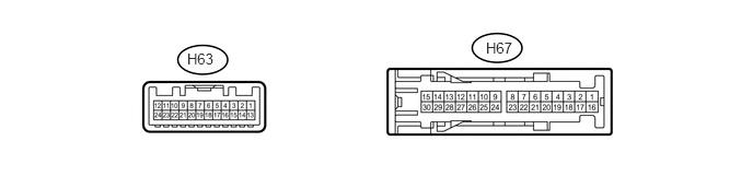
CHECK STEREO COMPONENT AMPLIFIER ASSEMBLY (for 9 Speakers)
4.625,0.375 4.948,0.542
0.323,0.167
10
false
H67
1.781,0.479 2.104,0.646
0.323,0.167
10
false
H63
| Terminal No. (Symbol) | Wiring Color | Terminal Description | Condition | Specification |
|---|---|---|---|---|
| H67-1 (+B) - H67-3 (GND) | W - BR | Power source | Always | 11 to 14 V |
| H67-3 (GND) - Body ground | BR - Body ground | Ground | Always | Below 1 Ω |
| H67-4 (WFL+) - H67-3 (GND) | P - BR | Sound signal (Front Left) | Audio system playing | A waveform synchronized with sound signals is output |
| H67-5 (WFR+) - H67-3 (GND) | LG - BR | Sound signal (Front Right) | Audio system playing | A waveform synchronized with voice signals is output |
| H67-7 (CTR+) - H67-3 (GND) | Y - BR | Sound signal (Front Center) | Audio system playing | A waveform synchronized with voice signals is output |
| H67-12 (FL+) - H67-3 (GND) | P - BR | Sound signal (Front Left) | Audio system playing | A waveform synchronized with sound signals is output |
| H67-13 (FR+) - H67-3 (GND) | LG - BR*1
R - BR*2 |
Sound signal (Front Right) | Audio system playing | A waveform synchronized with sound signals is output |
| H67-14 (RL+) - H67-3 (GND) | B - BR | Sound signal (Rear Left) | Audio system playing | A waveform synchronized with sound signals is output |
| H67-15 (RR+) - H67-3 (GND) | R - BR | Sound signal (Rear Right) | Audio system playing | A waveform synchronized with sound signals is output |
| H67-16 (+B2) - H67-3 (GND) | LG - BR | Power source | Always | 11 to 14 V |
| H67-18 (GND2) - Body ground | BR - Body ground | Ground | Always | Below 1 Ω |
| H67-19 (WFL-) - H67-3 (GND) | V - BR | Sound signal (Front Left) | Audio system playing | A waveform synchronized with sound signals is output |
| H67-20 (WFR-) - H67-3 (GND) | L - BR | Sound signal (Front Right) | Audio system playing | A waveform synchronized with voice signals is output |
| H67-22 (CTR-) - H67-3 (GND) | B - BR | Sound signal (Front Center) | Audio system playing | A waveform synchronized with sound signals is output |
| H67-27 (FL-) - H67-3 (GND) | V - BR | Sound signal (Front Left) | Audio system playing | A waveform synchronized with sound signals is output |
| H67-28 (FR-) - H67-3 (GND) | L - BR*1
W - BR*2 |
Sound signal (Front Right) | Audio system playing | A waveform synchronized with sound signals is output |
| H67-29 (RL-) - H67-3 (GND) | Y - BR | Sound signal (Rear Left) | Audio system playing | A waveform synchronized with sound signals is output |
| H67-30 (RR-) - H67-3 (GND) | W - BR | Sound signal (Rear Right) | Audio system playing | A waveform synchronized with sound signals is output |
| H63-1 (MUTE) - H67-3 (GND) | GR - BR | Mute signal | Ignition switch ACC, audio system playing | 2.0 V or higher |
| Audio system changing modes | Below 1 V | |||
| H63-2 (L-) - H67-3 (GND) | W - BR | Sound signal (Left) | Audio system playing | A waveform synchronized with sound signals is output |
| H63-3 (L+) - H67-3 (GND) | B - BR | Sound signal (Left) | Audio system playing | A waveform synchronized with sound signals is output |
| H63-4 (R-) - H67-3 (GND) | R - BR | Sound signal (Right) | Audio system playing | A waveform synchronized with sound signals is output |
| H63-5 (R+) - H67-3 (GND) | G - BR | Sound signal (Right) | Audio system playing | A waveform synchronized with sound signals is output |
| H63-6 (SLD) - Body ground | Shielded - Body ground | Shield ground | Always | Below 1 Ω |
| H63-7 (TX-) | W | AVC-LAN communication signal | - | - |
| H63-8 (TX+) | B | AVC-LAN communication signal | - | - |
| H63-11 (SPD) - H67-3 (GND) | R - BR | Vehicle speed signal | Ignition switch ON
Wheel being rotated |
Pulse generation |
| H63-12 (ACC) - H67-3 (GND) | GR - BR | Illumination power source (ACC) | Ignition switch ACC | 11 to 14 V |
| Ignition switch off | Below 1 V | |||
| H63-14 (II1-) - H67-3 (GND) | W - BR | Voice signal | Voice guidance sounding | A waveform synchronized with sound signals is output |
| H63-15 (II1+) - H67-3 (GND) | B - BR | Voice signal | Voice guidance sounding | A waveform synchronized with sound signals is output |
| H63-18 (SLD1) - Body ground | Shielded - Body ground | Shield ground | Always | Below 1 Ω |
| H63-24 (TMUT) - H67-3 (GND)*2 | P - BR | Mute signal | Audio system playing | 3.5 V or higher |
| Emergency call mode | Below 1 V |
*1: w/o Telematics Transceiver
*2: w/ Telematics Transceiver
TELEMATICS TRANSCEIVER (w/ Telematics Transceiver)
Click hereAudio / Visual / Telematics>TELEMATICS>TELEMATICS SYSTEM>TERMINALS OF ECU