RM27T0E
_56
Audio / Visual / Telematics
_053722
PARK ASSIST / MONITORING
_0328214
MULTI-TERRAIN MONITOR SWITCH
G
PARK ASSIST / MONITORING MULTI-TERRAIN MONITOR SWITCH INSPECTION
PROCEDURE

 84721B
1.INSPECT PANORAMIC VIEW MONITOR SWITCH (MULTI-TERRAIN MONITOR SWITCH)
a.
1.479,1.146 0.927,0.531
true
1.958,1.146 2.531,0.521
true
1.302,1.292 0.823,1.771
true
2.146,1.281 2.625,1.76
true
0.104,0.083 0.385,0.313
0.281,0.229
10
false
*a
0.604,0.448 1.01,0.719
0.406,0.271
10
false
ECU
2.594,0.458 2.813,0.698
0.219,0.24
10
false
E
0.542,1.729 0.948,2
0.406,0.271
10
false
ILL+
2.677,1.708 3.083,1.979
0.406,0.271
10
false
ILL-
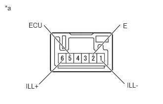
| *a | Component without harness connected
(Multi-terrain Monitor Switch) |
Measure the resistance according to the value(s) in the table below.
- Standard Resistance:
Tester Connection Switch Condition Specified Condition 5 (ECU) - 2 (E) Panoramic view monitor switch (multi-terrain monitor switch) on Below 1 Ω 5 (ECU) - 2 (E) Panoramic view monitor switch (multi-terrain monitor switch) off 10 kΩ or higher
If the result is not as specified, replace the panoramic view monitor switch (multi-terrain monitor switch).
b.
Apply battery voltage to the connector and check the LED illumination.
- OK:
Measurement Condition Specified Condition Battery positive (+) → Terminal 6 (ILL+)
Battery negative (-) → Terminal 1 (ILL-)LED illuminates
If the result is not as specified, replace the panoramic view monitor switch (multi-terrain monitor switch).