AXLE AND DIFFERENTIAL REAR DIFFERENTIAL LOCK ACTUATOR INSPECTION
PROCEDURE

 41450
1.INSPECT DIFFERENTIAL LOCK SHIFT ACTUATOR
Check the free to lock switch.
Connect lines via a relay as shown in the illustration and check that the actuator fork moves from the free to the lock position.
- NOTICE:
- ·
Make sure to perform this inspection with the actuator removed from the vehicle. If this inspection is performed with the actuator installed to the vehicle, the actuator will be damaged.
·When inspecting the actuator, make sure to operate it with the lines connected via a relay. If the lines are not connected via a relay and battery voltage is directly applied to the actuator, the actuator will be damaged.
- HINT:
-
When performing the operation described above, use the DEF relay.
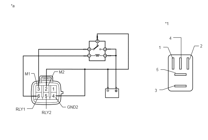
| *1 | DEF Relay | - | - |
| *a | Front view of wire harness connector
(to Differential Lock Shift Actuator) |
- | - |
After the free to lock switch is complete, check the limit switch.
Measure the resistance according to the value(s) in the table below.
- Standard Resistance:
Tester Connection Condition Specified Condition 5 (RLY2) - 4 (GND2) After free to lock switch is complete Below 12.5 Ω 6 (RLY1) - 4 (GND2) After free to lock switch is complete 500 kΩ or higher
If the result is not as specified, replace the differential lock shift actuator assembly.
Check the lock to free switch.
Connect lines via a relay as shown in the illustration and check that the actuator fork moves from the lock to the free position.
- NOTICE:
- ·
Make sure to perform this inspection with the actuator removed from the vehicle. If this inspection is performed with the actuator installed to the vehicle, the actuator will be damaged.
·When inspecting the actuator, make sure to operate it with the lines connected via a relay. If the lines are not connected via a relay and battery voltage is directly applied to the actuator, the actuator will be damaged.
- HINT:
-
When performing the operation described above, use the DEF relay.
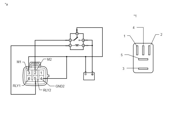
| *1 | DEF Relay | - | - |
| *a | Front view of wire harness connector
(to Differential Lock Shift Actuator) |
- | - |
After the lock to free switch is complete, check the limit switch.
Measure the resistance according to the value(s) in the table below.
- Standard Resistance:
Tester Connection Condition Specified Condition 5 (RLY2) - 4 (GND2) After lock to free switch is complete 500 kΩ or higher 6 (RLY1) - 4 (GND2) After lock to free switch is complete Below 12.5 Ω
If the result is not as specified, replace the differential lock shift actuator assembly.