PARK ASSIST / MONITORING PARKING ASSIST MONITOR SYSTEM(for Camera built-in ECU) Reverse Signal Circuit
DESCRIPTION
The navigation receiver assembly receives a reverse signal from the park/neutral position switch assembly.
WIRING DIAGRAM
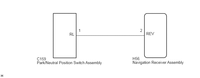
CAUTION / NOTICE / HINT
- NOTICE:
- ·
If the cable was disconnected from and reconnected to the negative (-) battery terminal, the estimated course lines may not be displayed on the image of the area behind the vehicle. In this case, perform "Correct the Steering Angle Neutral Point" (See page Audio / Visual / Telematics>PARK ASSIST / MONITORING>PARKING ASSIST MONITOR SYSTEM (for Camera built-in ECU)>INITIALIZATION).
·Depending on the parts that are replaced or operations that are performed during vehicle inspection or maintenance, calibration of other systems as well as the parking assist monitor system may be needed (See page Audio / Visual / Telematics>PARK ASSIST / MONITORING>PARKING ASSIST MONITOR SYSTEM (for Camera built-in ECU)>CALIBRATION).
PROCEDURE
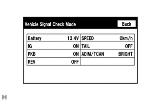
Enter the "Function check/setting I" mode and select "Vehicle Signal".
Check that the display changes between ON and OFF according to the shift lever position.
| Shift Lever Position | Display |
|---|---|
| R | ON |
| Except R | OFF |
- HINT:
-
This display is updated once per second. As a result, it is normal for the display to lag behind the actual shift lever position.
OK
NG
Remove the park/neutral position switch assembly (See page Drivetrain>AC60F (AUTOMATIC TRANSMISSION / TRANSAXLE)>PARK / NEUTRAL POSITION SWITCH>REMOVAL).
Inspect the park/neutral position switch assembly (See page Drivetrain>AC60F (AUTOMATIC TRANSMISSION / TRANSAXLE)>PARK / NEUTRAL POSITION SWITCH>INSPECTION).
| Result | Proceed to |
|---|---|
| OK (for Navigation Receiver Type) | A |
| OK (for Radio and Display Type) | B |
| NG | C |
A
C
(See pageDrivetrain>AC60F (AUTOMATIC TRANSMISSION / TRANSAXLE)>PARK / NEUTRAL POSITION SWITCH>REMOVAL)
Disconnect the H56 navigation receiver assembly connector.
Disconnect the C159 park/neutral position switch assembly connector.
Measure the resistance according to the value(s) in the table below.
- Standard Resistance:
Tester Connection Condition Specified Condition H56-2 (REV) - C159-1 (RL) Always Below 1 Ω H56-2 (REV) - Body ground Always 10 kΩ or higher
OK
NG