1GD-FTV EMISSION CONTROL MONOLITHIC CONVERTER(w/o DPF) INSTALLATION
PROCEDURE

 25051
1.INSTALL EXHAUST MANIFOLD CONVERTER SUB-ASSEMBLY
Set a new gasket and the exhaust manifold converter sub-assembly to the turbocharger sub-assembly.
Temporarily install the exhaust pipe support stay to the cylinder block sub-assembly and exhaust manifold converter sub-assembly with the 3 bolts.
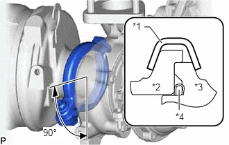
| *1 | Exhaust Pipe Clamp |
| *2 | Exhaust Manifold Converter Sub-assembly |
| *3 | Turbocharger Sub-assembly |
| *4 | Gasket |
Install a new exhaust pipe clamp to the exhaust manifold converter sub-assembly with a new nut.
- Torque:
- 18 N*m (184 kgf*cm, 13 ft.*lbf)
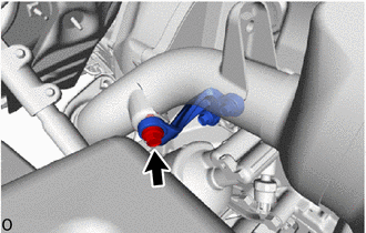
Temporarily install the exhaust pipe support stay to the exhaust manifold converter sub-assembly with the bolt.
- Torque:
- 8.5 N*m (87 kgf*cm, 75 in.*lbf)
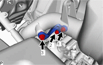
Tighten the 3 bolts and install the exhaust pipe support stay to the cylinder block sub-assembly and exhaust manifold converter sub-assembly in the order shown in the illustration.
- Torque:
- 38 N*m (387 kgf*cm, 28 ft.*lbf)
17118
2.INSTALL NO. 2 EXHAUST PIPE SUPPORT STAY
Temporarily install the No. 2 exhaust pipe support stay to the cylinder block sub-assembly and exhaust manifold converter sub-assembly with the bolt and 2 new nuts.
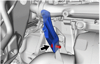
Temporarily install the No. 2 exhaust pipe support stay to the exhaust manifold converter sub-assembly with the bolt.
- Torque:
- 8.5 N*m (87 kgf*cm, 75 in.*lbf)
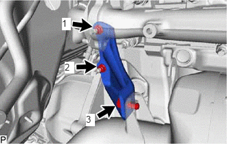
Tighten the bolt and 2 nuts and install the No. 2 exhaust pipe support stay to the cylinder block sub-assembly and exhaust manifold converter sub-assembly in the order shown in the illustration.
- Torque:
- 38 N*m (387 kgf*cm, 28 ft.*lbf)
17271
3.INSTALL NO. 1 TURBO INSULATOR
Install the No. 1 turbo insulator to the exhaust manifold and turbocharger sub-assembly with the 3 bolts.
- Torque:
- 12 N*m (122 kgf*cm, 9 ft.*lbf)
17167
4.INSTALL NO. 1 EXHAUST MANIFOLD HEAT INSULATOR
Install the No. 1 exhaust manifold heat insulator to the exhaust manifold with the 3 bolts.
- Torque:
- 12 N*m (122 kgf*cm, 9 ft.*lbf)
17410
5.INSTALL FRONT EXHAUST PIPE ASSEMBLY