RM27T0E
_51
Engine / Hybrid System
_053696
CRUISE CONTROL
_0438250
CRUISE CONTROL SYSTEM(except i-ART)
U
CRUISE CONTROL CRUISE CONTROL SYSTEM(except i-ART) TERMINALS OF ECM
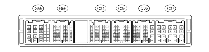
CHECK ECM (for 1GR-FE)
1.188,0.208 1.458,0.396
0.271,0.188
10
false
G55
2.021,0.208 2.365,0.396
0.344,0.188
10
false
G56
3.333,0.208 3.698,0.396
0.365,0.188
10
false
C34
4.052,0.208 4.448,0.479
0.396,0.271
10
false
C35
4.823,0.198 5.198,0.469
0.375,0.271
10
false
C36
5.729,0.208 6.115,0.479
0.385,0.271
10
false
C37
a.
Disconnect the C34, C36 G55 and G56 ECM connectors.
b.
Measure the voltage and resistance according to the value(s) in the table below.
| Terminal No. (Symbol) | Wiring Color | Terminal Description | Condition | Specified Condition |
|---|---|---|---|---|
| C34-27 (D) - C36-12 (E1)*2 | B - BR | Clutch switch signal | Ignition switch ON, clutch pedal released | 11 to 14 V |
| Ignition switch ON, clutch pedal depressed | Below 1 V | |||
| G56-34 (ST1-) - Body ground*1
G55-8 (ST1-) - Body ground*2 |
B - Body ground | Stop light switch signal circuit | Ignition switch ON, brake pedal released | 11 to 14 V |
| Ignition switch ON, brake pedal depressed | Below 1 V | |||
| G56-35 (STP) - Body ground*1
G56-18 (STP) - Body ground*2 |
V - Body ground | Stop light switch signal circuit | Brake pedal depressed | 11 to 14 V |
| Brake pedal released | Below 1 V | |||
| G56-1 (CCS) - Body ground*1
G56-11 (CCS) - Body ground*2 |
B - Body ground | Cruise control main switch circuit | Cruise control main switch on | Below 2.5 Ω |
| Cruise control main switch off | 10 kΩ or higher | |||
| +RES switch held on | 235 to 245 Ω | |||
| -SET switch held on | 617 to 643 Ω | |||
| CANCEL switch held on | 1509 to 1571 Ω |
*1: for Automatic Transmission
*2: for Manual Transmission
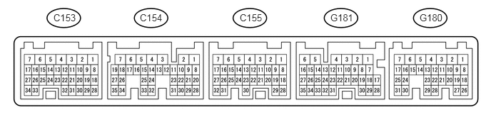
CHECK ECM (for 2TR-FE)
0.781,0.177 1.177,0.417
0.396,0.24
10
false
C153
2.042,0.177 2.427,0.406
0.385,0.229
10
false
C154
3.5,0.177 4,0.406
0.5,0.229
10
false
C155
6.125,0.177 6.615,0.406
0.49,0.229
10
false
G180
4.823,0.177 5.302,0.406
0.479,0.229
10
false
G181
a.
Disconnect the G180 and G181 ECM connectors.
b.
Measure the voltage and resistance according to the value(s) in the table below.
| Terminal No. (Symbol) | Wiring Color | Terminal Description | Condition | Specified Condition |
|---|---|---|---|---|
| G180-11 (ST1-) - Body ground | B - Body ground | Stop light switch signal circuit | Ignition switch ON, brake pedal released | 11 to 14 V |
| Ignition switch ON, brake pedal depressed | Below 1 V | |||
| G180-10 (STP) - Body ground | V - Body ground | Stop light switch signal circuit | Brake pedal depressed | 11 to 14 V |
| Brake pedal released | Below 1 V | |||
| G181-22 (CCS) - Body ground | B - Body ground | Cruise control main switch circuit | Cruise control main switch on | Below 2.5 Ω |
| Cruise control main switch off | 10 kΩ or higher | |||
| +RES switch held on | 235 to 245 Ω | |||
| -SET switch held on | 617 to 643 Ω | |||
| CANCEL switch held on | 1509 to 1571 Ω |