AUDIO / VIDEO REAR SEAT ENTERTAINMENT SYSTEM Illumination Circuit
DESCRIPTION
Power is supplied to the television display assembly illumination when the light control switch is in the TAIL or HEAD position.
WIRING DIAGRAM
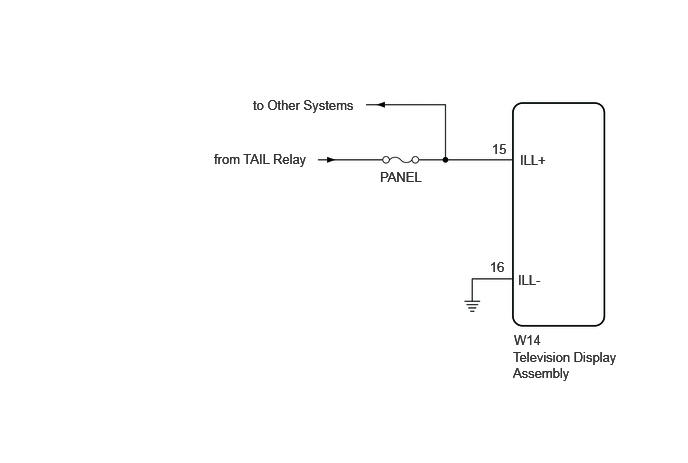
CAUTION / NOTICE / HINT
- NOTICE:
-
Inspect the fuse for circuits related to this system before performing the following inspection procedure.
PROCEDURE
Check if the rheostat function operates normally.
- OK:
The rheostat function operates normally.
- Result:
Proceed to OK NG
OK
NG
Click hereVehicle Interior>METER / GAUGE / DISPLAY>METER / GAUGE SYSTEM>HOW TO PROCEED WITH TROUBLESHOOTING
Check if the instrument panel illumination comes on normally.
- OK:
The instrument panel illumination comes on normally.
- Result:
Proceed to OK NG
OK
NG
Click hereVehicle Interior>LIGHTING (INT)>LIGHTING SYSTEM (except 5L-E)>HOW TO PROCEED WITH TROUBLESHOOTING
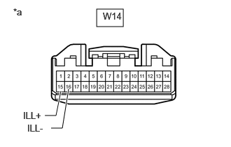
| *a | Front view of wire harness connector
(to Television Display Assembly) |
Disconnect the television display assembly connector.
Measure the voltage according to the value(s) in the table below.
- Standard Voltage:
Tester Connection Switch Condition Specified Condition W14-15 (ILL+) - Body ground Ignition switch off, light control switch TAIL 11 to 14 V
Measure the resistance according to the value(s) in the table below.
- Standard Resistance:
Tester Connection Condition Specified Condition W14-16 (ILL-) - Body ground Always Below 1 Ω
- Result:
Proceed to OK NG
OK
Click hereAudio / Visual / Telematics>AUDIO / VIDEO>REAR SEAT ENTERTAINMENT SYSTEM>PROBLEM SYMPTOMS TABLE
NG