RM27T0E
_55
Steering
_053718
STEERING COLUMN
_0260959
STEERING WHEEL
G
STEERING COLUMN STEERING WHEEL INSPECTION
PROCEDURE

 84250A
1.INSPECT STEERING PAD SWITCH ASSEMBLY
Measure the resistance according to the value(s) in the table below.
a.
Type A:
i.
If the result is not as specified, replace the steering switch.
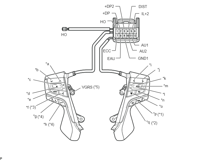
2.156,2.906 1.823,2.385
true
1.865,2.906 1.448,2.573
true
2.063,3.094 1.208,2.906
true
2.052,3.188 1.177,3.396
true
1.906,3.323 1.198,3.604
true
2.208,3.406 1.313,3.854
true
2,3.688 1.479,4.115
true
2.219,3.76 1.792,4.406
true
4.885,2.885 5.385,2.396
true
5.177,2.896 5.646,2.552
true
5.01,3.094 5.865,2.875
true
5,3.188 5.865,3.396
true
5.104,3.354 5.802,3.635
true
4.833,3.406 5.729,3.854
true
5.021,3.708 5.542,4.135
true
4.865,3.771 5.292,4.417
true
4.24,1.083 4.063,0.76
4.063,0.76 3.906,0.76
true
4.375,1.073 4.198,0.479
4.198,0.479 4.063,0.479
true
4.521,1.073 4.354,0.229
4.354,0.229 4.198,0.229
true
4.667,1.083 4.792,0.229
4.792,0.229 4.938,0.229
true
4.813,1.073 4.927,0.49
4.927,0.49 5.063,0.49
true
4.25,1.354 4.198,1.844
4.198,1.844 4.073,1.844
true
4.385,1.344 4.375,2.115
4.375,2.115 4.219,2.115
true
4.521,1.354 4.708,2.115
4.708,2.115 4.938,2.115
true
4.656,1.333 4.823,1.833
4.823,1.833 4.979,1.833
true
4.781,1.354 4.906,1.646
4.906,1.646 5.063,1.646
true
2.667,3.354 2.927,3.208
true
5.104,3.146 5.906,3.146
true
1.656,2.24 1.927,2.448
0.271,0.208
10
false
*a
1.271,2.458 1.542,2.667
0.271,0.208
10
false
*b
1.01,2.813 1.281,3.021
0.271,0.208
10
false
*c
0.958,3.323 1.229,3.531
0.271,0.208
10
false
*d
1,3.542 1.271,3.75
0.271,0.208
10
false
*e
0.948,3.833 1.354,4.052
0.406,0.219
10
false
*f
1.208,4.146 1.625,4.375
0.417,0.229
10
false
*g
1.583,4.448 1.99,4.656
0.406,0.208
10
false
*h
5.427,2.281 5.698,2.49
0.271,0.208
10
false
*i
5.729,2.448 6,2.656
0.271,0.208
10
false
*j
5.917,2.771 6.188,2.979
0.271,0.208
10
false
*k
5.917,3.354 6.188,3.563
0.271,0.208
10
false
*l
5.854,3.563 6.125,3.771
0.271,0.208
10
false
*n
5.948,3.042 6.219,3.25
0.271,0.208
10
false
*m
5.323,4.365 5.594,4.573
0.271,0.208
10
false
*q
5.792,3.792 6.063,4
0.271,0.208
10
false
*o
5.573,4.063 5.844,4.271
0.271,0.208
10
false
*p
3.646,0.708 4.01,0.896
0.365,0.188
10
false
HO
3.729,0.396 4.094,0.583
0.365,0.188
10
false
+DP
3.802,0.146 4.25,0.333
0.448,0.188
10
false
+DP2
5.042,0.156 5.49,0.344
0.448,0.188
10
false
DIST
5.146,0.417 5.594,0.604
0.448,0.188
10
false
IL+2
3.75,1.771 4.198,1.958
0.448,0.188
10
false
ECC
3.906,2.052 4.25,2.271
0.344,0.219
10
false
EAU
5.021,2.042 5.469,2.229
0.448,0.188
10
false
GND1
5.073,1.781 5.521,1.969
0.448,0.188
10
false
AU2
5.135,1.563 5.583,1.75
0.448,0.188
10
false
AU1
2.979,3.094 3.708,3.323
0.729,0.229
10
false
VGRS
2.229,1.177 2.594,1.365
0.365,0.188
10
false
HO
5.729,4.083 6,4.292
0.271,0.208
10
false
(*1)
5.5,4.396 5.771,4.604
0.271,0.208
10
false
(*2)
1.75,4.448 1.99,4.656
0.24,0.208
10
false
(*4)
1.365,4.167 1.646,4.375
0.281,0.208
10
false
(*4)
1.083,3.823 1.354,4.021
0.271,0.198
10
false
(*3)
3.396,3.083 3.677,3.292
0.281,0.208
10
false
(*5)
| *1 | with ACC switch | *2 | with LDA switch |
| *3 | with Voice switch | *4 | w/ Hook Switch |
| *5 | with VGRS | - | - |
| *a | Seek+ Switch | *b | Seek- Switch |
| *c | Volume+ Switch | *d | Volume- Switch |
| *e | MODE Switch | *f | Voice Switch |
| *g | Off Hook Switch | *h | On Hook Switch |
| *i | LEFT | *j | RIGHT |
| *k | UP | *l | DOWN |
| *m | ENTER | *n | BACK |
| *o | TOP | *p | ACC |
| *q | LDA | - | - |
- Standard Resistance:
Tester Connection Switch Condition Specified Condition 11 (AU1) - 8 (EAU) No switch is pushed 95 to 105 kΩ Seek+ switch pushed Below 2.5 Ω Seek- switch pushed 313 to 345 Ω Volume+ switch pushed 950 to 1050 Ω Volume- switch pushed 2955 to 3265 Ω 10 (AU2) - 8 (EAU) No switch is pushed 95 to 105 kΩ Mode switch pushed Below 2.5 Ω Voice switch pushed 2955 to 3265 Ω On Hook switch pushed 313 to 345 Ω Off Hook switch pushed 950 to 1050 Ω 2 (+DP) - 8 (EAU) No switch is pushed 95 to 105 kΩ ENTER switch pushed Below 2.5 Ω BACK switch pushed 950 to 1050 Ω TOP switch pushed 313 to 345 Ω 3 (+DP2) - 8 (EAU) No switch is pushed 95 to 105 kΩ Left switch pushed Below 2.5 Ω Right switch pushed 2955 to 3265 Ω Up switch pushed 313 to 345 Ω Down switch pushed 950 to 1050 Ω 4 (DIST) - 7 (ECC) No switch is pushed 1MΩ or higher ACC switch pushed Below 2.5 Ω LDA switch pushed 228 to 252 Ω HO - 1 (HO) Always Below 2.5 Ω VGRS - 9 (GND1) Always Below 2.5 Ω
b.
Type B:
i.
If the result is not as specified, replace the steering switch.
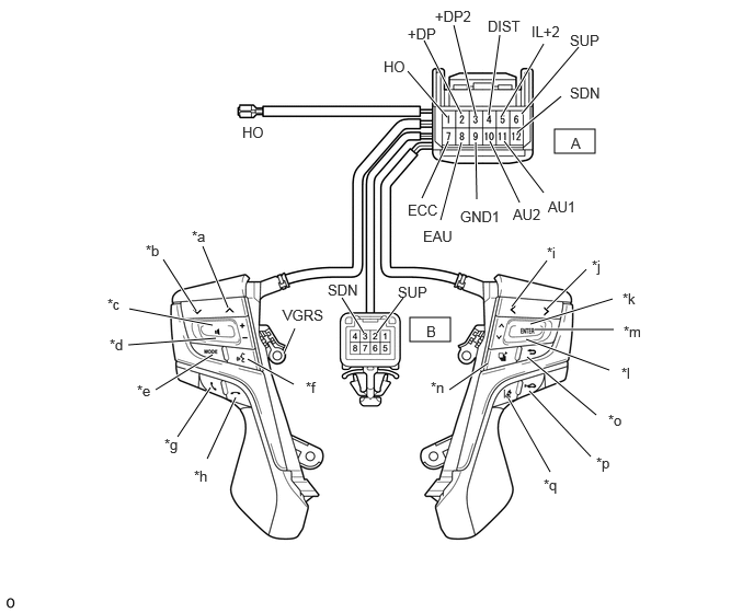
5.271,1.229 5.656,1.458
0.385,0.229
3.896,3.021 4.281,3.25
0.385,0.229
4.25,1.115 3.875,0.677
true
4.385,1.083 4.031,0.385
true
4.521,1.094 4.313,0.24
true
4.646,1.094 4.75,0.333
true
4.76,1.115 5.167,0.417
true
4.01,1.885 4.26,1.344
true
4.188,2.094 4.385,1.354
true
4.531,1.896 4.521,1.354
true
4.938,1.927 4.656,1.344
true
5.167,1.833 4.792,1.344
true
2.167,2.927 1.927,2.344
true
1.865,2.958 1.552,2.469
true
2.021,3.094 1.229,2.938
true
1.219,3.281 2.052,3.219
true
1.479,3.708 2.021,3.375
true
1.688,4.156 2,3.688
true
1.969,4.365 2.24,3.781
true
2.792,3.656 2.354,3.417
true
4.865,2.917 5.198,2.479
true
5.198,2.938 5.573,2.563
true
5.042,3.083 5.823,2.844
true
5.083,3.135 5.833,3.135
true
5,3.229 5.792,3.521
true
5.667,3.948 5.01,3.396
true
4.271,3.708 4.635,3.458
true
5.615,4.344 5.031,3.719
true
5.229,4.49 4.833,3.792
true
5.333,0.917 4.917,1.26
true
3.458,3.167 3.25,2.833
true
3.583,3.167 3.833,2.833
true
4.958,1.083 5.5,0.448
true
2.802,3.125 2.698,3.365
true
2.302,1.177 2.615,1.375
0.313,0.198
10
false
HO
3.646,0.552 3.958,0.75
0.313,0.198
10
false
HO
3.875,0.24 4.333,0.438
0.458,0.198
10
false
+DP
4.135,0.073 4.75,0.271
0.615,0.198
10
false
+DP2
4.635,0.167 5.25,0.365
0.615,0.198
10
false
DIST
5.052,0.219 5.667,0.417
0.615,0.198
10
false
IL+2
3.875,1.917 4.292,2.094
0.417,0.177
10
false
ECC
4.021,2.167 4.479,2.365
0.458,0.198
10
false
EAU
4.375,1.979 4.99,2.177
0.615,0.198
10
false
GND1
4.875,1.958 5.333,2.156
0.458,0.198
10
false
AU2
5.208,1.885 5.667,2.083
0.458,0.198
10
false
AU1
5.427,1.281 5.583,1.479
0.156,0.198
10
false
A
1.823,2.167 2.135,2.365
0.313,0.198
10
false
*a
1.385,2.302 1.698,2.5
0.313,0.198
10
false
*b
1.021,2.813 1.333,3.01
0.313,0.198
10
false
*c
1.042,3.198 1.354,3.396
0.313,0.198
10
false
*d
1.302,3.635 1.615,3.833
0.313,0.198
10
false
*e
1.563,4.146 1.875,4.344
0.313,0.198
10
false
*g
1.844,4.448 2.156,4.646
0.313,0.198
10
false
*h
2.906,3.604 3.219,3.802
0.313,0.198
10
false
*f
5.198,2.323 5.51,2.521
0.313,0.198
10
false
*i
5.625,2.448 5.938,2.646
0.313,0.198
10
false
*j
5.917,2.76 6.229,2.958
0.313,0.198
10
false
*k
5.927,3.073 6.24,3.271
0.313,0.198
10
false
*m
5.906,3.469 6.135,3.646
0.229,0.177
10
false
*l
5.781,3.917 6.094,4.115
0.313,0.198
10
false
*o
4.094,3.604 4.406,3.802
0.313,0.198
10
false
*n
5.667,4.323 5.979,4.521
0.313,0.198
10
false
*p
5.167,4.531 5.479,4.729
0.313,0.198
10
false
*q
4.052,3.073 4.25,3.25
0.198,0.177
10
false
B
5.417,0.802 6.031,1
0.615,0.198
10
false
SDN
3.115,2.677 3.729,2.875
0.615,0.198
10
false
SDN
3.781,2.698 4.396,2.896
0.615,0.198
10
false
SUP
5.417,0.302 6.031,0.5
0.615,0.198
10
false
SUP
2.688,2.917 3.302,3.115
0.615,0.198
10
false
VGRS
| *a | Seek+ Switch | *b | Seek- Switch |
| *c | Volume+ Switch | *d | Volume- Switch |
| *e | MODE Switch | *f | Voice Switch |
| *g | Off Hook Switch | *h | On Hook Switch |
| *i | LEFT | *j | RIGHT |
| *k | UP | *l | DOWN |
| *m | ENTER | *n | TOP |
| *o | BACK | *p | ACC |
| *q | LDA | - | - |
- Standard Resistance:
Tester Connection Switch Condition Specified Condition A11 (AU1) - A8 (EAU) No switch is pushed 95 to 105 kΩ Seek+ switch pushed Below 2.5 Ω Seek- switch pushed 313 to 345 Ω Volume+ switch pushed 950 to 1050 Ω Volume- switch pushed 2955 to 3265 Ω A10 (AU2) - A8 (EAU) No switch is pushed 95 to 105 kΩ Mode switch pushed Below 2.5 Ω Voice switch pushed 2955 to 3265 Ω On Hook switch pushed 313 to 345 Ω Off Hook switch pushed 950 to 1050 Ω A2 (+DP) - A8 (EAU) No switch is pushed 95 to 105 kΩ ENTER switch pushed Below 2.5 Ω BACK switch pushed 950 to 1050 Ω TOP switch pushed 313 to 345 Ω A3 (+DP2) - A8 (EAU) No switch is pushed 95 to 105 kΩ Left switch pushed Below 2.5 Ω Right switch pushed 2955 to 3265 Ω Up switch pushed 313 to 345 Ω Down switch pushed 950 to 1050 Ω A4 (DIST) - A7 (ECC) No switch is pushed 1MΩ or higher ACC switch pushed Below 2.5 Ω LDA switch pushed 228 to 252 Ω A6 (SUP) - B2 (SUP) Always Below 2.5 Ω A12 (SDN) - B3 (SDN) Always Below 2.5 Ω A1 (HO) - 1 (HO) Always Below 2.5 Ω VGRS - A9 (GND1) Always Below 2.5 Ω
c.
Connect the battery positive (+) lead to terminal 5 (IL+2) and the negative (-) lead to terminal 8 (EAU) of the steering pad switch connector.
d.
Check that the switch illumination comes on.
- OK:
Steering pad switch illumination comes on.
If the result is not as specified, replace the steering pad switch.