1GD-FTV ENGINE CONTROL ECD SYSTEM FREEZE FRAME DATA
DESCRIPTION
The ECM records vehicle and driving condition information as freeze frame data the moment a DTC is stored. When troubleshooting, freeze frame data can be helpful in determining whether the vehicle was moving or stationary, if the engine was warmed up or not, and other data from the time the malfunction occurred.
- HINT:
-
If it is impossible to duplicate the problem even though a DTC is stored, confirm the freeze frame data.
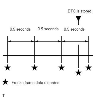
The ECM records engine conditions in the form of freeze frame data every 0.5 seconds. Using the GTS, 5 separate sets of freeze frame data can be checked.
3 data sets from before the DTC was stored
1 data set from when the DTC was stored
1 data set from after the DTC was stored
These data sets can be used to simulate the condition of the vehicle from around the time of the occurrence of the malfunction. The data may assist in identifying the cause of the malfunction, and in judging whether it was temporary or not.
LIST OF FREEZE FRAME DATA
| Tester Display |
|---|
| Total Distance Traveled |
| Total Distance Traveled - Unit |
| Vehicle Speed |
| Target Idle Engine Speed |
| Engine Speed |
| Calculate Load |
| Mass Air Flow Sensor |
| Atmospheric Pressure |
| Intake Manifold Absolute Pressure |
| Intake Manifold Absolute Pressure Supported |
| Coolant Temperature |
| Intake Air Temperature |
| Intake Air Temperature B1S1 (Turbo) |
| Intake Air Temperature B1S1 (Turbo) Supported |
| Intake Air Temperature B1S2 (Turbo) Supported |
| Intake Air Temperature B1S1 |
| Intake Air Temperature B1S2 |
| Intake Air Temperature B1S1 Supported |
| Intake Air Temperature B1S2 Supported |
| Intake Air Temperature B1S3 Supported |
| Intake Air Temperature B2S1 Supported |
| Intake Air Temperature B2S2 Supported |
| Intake Air Temperature B2S3 Supported |
| Ambient Temperature |
| Engine Run Time |
| IG-ON Coolant Temperature |
| Initial Engine Coolant Temperature |
| IG-ON Intake Air Temperature |
| Initial Engine Intake Air Temperature |
| Battery Voltage |
| Battery Sensor Voltage |
| BATT Voltage |
| Alternate Duty Ratio |
| Glow Relay Request Bank 1 |
| Glow Control Unit Duty |
| Engine Oil Pressure |
| Engine Oil Pressure VSV |
| Accel Position |
| Accelerator Position Sensor No.1 Voltage % |
| Accelerator Position Sensor No.2 Voltage % |
| Actual Throttle Position Bank 1 |
| Target Throttle Position Bank 1 |
| Actual Throttle Position Bank 1 Supported |
| Actual Throttle Position Bank 2 Supported |
| Target Throttle Position Bank 1 Supported |
| Target Throttle Position Bank 2 Supported |
| Throttle Position Sensor No.1 Voltage % |
| Diesel Throttle Motor Duty Bank 1 |
| Diesel Throttle Target Angle Bank 1 |
| Throttle Close Learning Value Bank 1 |
| Neutral Control |
| N Range Status |
| Electric Duty Feedback Value |
| PS Duty Feedback Value |
| Total Injection Volume |
| Target Injection Volume |
| Injection Feedback Volume for Idle |
| Injection Volume Cylinder #1 |
| Injection Feedback Value #1 |
| Injection Feedback Value #2 |
| Injection Feedback Value #3 |
| Injection Feedback Value #4 |
| Injection Volume #1 |
| Injection Volume #2 |
| Injection Volume #3 |
| Injection Volume #4 |
| Pilot 1 Injection Period |
| Pilot 2 Injection Period |
| Pre Injection Period |
| Main Injection Period |
| After Injection Period |
| Pilot 1 Injection Timing |
| Pilot 2 Injection Timing |
| Pre Injection Timing |
| Main Injection Timing |
| After Injection Timing |
| i-ART Learning Status #1 |
| i-ART Learning Status #2 |
| i-ART Learning Status #4 |
| i-ART Learning Status History #1 |
| i-ART Learning Status History #2 |
| i-ART Learning Status History #3 |
| i-ART Learning Status History #4 |
| Injector Leaking Count #1 |
| Injector Leaking Count #2 |
| Injector Leaking Count #3 |
| Injector Leaking Count #4 |
| Injection Pressure Correction |
| PCV Energization Timing |
| Target Fuel Pressure (High) |
| Target Fuel Pressure (High) Supported |
| Target Fuel Pressure (Low) / Target Fuel Pressure 2 |
| Target Fuel Pressure (Low) / Target Fuel Pressure 2 Supported |
| Fuel Pressure (High) |
| Fuel Pressure (High) Supported |
| Fuel Pressure (Low) / Fuel Pressure 2 |
| Fuel Pressure (Low) / Fuel Pressure 2 Supported |
| Fuel Pressure #1 |
| Fuel Pressure #2 |
| Fuel Pressure #3 |
| Fuel Pressure #4 |
| Fuel Temperature #1 |
| Fuel Temperature #2 |
| Fuel Temperature #3 |
| Fuel Temperature #4 |
| Fuel Return Temperature |
| Fuel Injection Valve + Output Signal Bank 1 |
| Fuel Injection Valve - Output Signal Bank 1 |
| Engine Fuel Rate |
| Vehicle Fuel Rate |
| Injection Control Malfunction (Target Injection Volume 1) |
| Injection Control Malfunction (Target Injection Volume 2) |
| Injection Control Malfunction (Target Injection Volume 3) |
| Injection Control Malfunction (Injector Current-Carrying Time 1) |
| Injection Control Malfunction (Injector Current-Carrying Time 2) |
| Injection Control Malfunction (Injector Current-Carrying Time 3) |
| Injection Control Malfunction (Fail Safe Function) |
| Pump Difference Angle Learning Value |
| Current Fuel Type |
| Target EGR Valve Position No.1 |
| Target EGR Valve Position No.1 Supported |
| EGR Step Position Bank 1 |
| Actual EGR Valve Position No.1 |
| Actual EGR Valve Position No.1 Supported |
| EGR Rate Differential (Actual-Target) |
| Target EGR Valve Position No.2 Supported |
| Actual EGR Valve Position No.2 Supported |
| EGR Cooler Bypass VSV |
| EGR Cooler Bypass Position |
| EGR Close Learning Value Bank 1 |
| EGR Position Sensor Bank 1 |
| Target Boost Pressure |
| Target Boost Pressure Supported |
| Target Boost Pressure2 Supported |
| Boost Pressure Sensor Supported |
| Boost Pressure Sensor2 Supported |
| Target VN Turbo Position Bank 1 |
| Actual VN Turbo Position Bank 1 |
| Target VN Turbo Position Bank 1 Supported |
| Actual VN Turbo Position Bank 1 Supported |
| Target VN Turbo Position Bank 2 Supported |
| Actual VN Turbo Position Bank 2 Supported |
| VN Position Sensor Out Bank 1 |
| VN Close Learn Value Bank 1 |
| VN Turbo Minimum Angle |
| VN Turbo Maximum Angle |
| Turbo Charger Step Motor Bank 1 |
| Starter SW |
| Neutral Position SW |
| Transfer L4 |
| Stop Light SW |
| Immobiliser Communication |
| Clogged Fuel Filter Switch |
| Cruise Main SW |
| TC Terminal |
| MIL ON Run Distance |
| Running Time from MIL ON |
| Time after DTC Cleared |
| Distance from DTC Cleared |
| Warmup Cycle Cleared DTC |
| Distance Traveled from Last Battery Cable Disconnect |
| IG OFF Elapsed Time |
| Soak IC Current Timer Value |
| Engine Speed (Starter Off) |
| Starter Count |
| Run Distance of Previous Trip |
| Engine Starting Time |
| IG ON Time |
| Glow Request Lighting Time |
| Engine Coolant Temperature High |
| Common Rail Pressure Low |
| Boost Pressure Low |
| MAF Low |
| MAF/Estimate MAF Ratio |
| Minimum Engine Speed |
| Compression Leakage Count |
| Plural Cylinders Rough Idle |
| Rough Idle Cylinder #1 |
| Rough Idle Cylinder #2 |
| Rough Idle Cylinder #3 |
| Rough Idle Cylinder #4 |
| Battery Current |
| Battery Temperature |
| Alternator Output Duty Ratio |
| Alternator Voltage - Non Active Test |
| Voltage of Alternator |
| Battery Charging Rate Accuracy |
| Battery Status of Full Charge |
| Battery Dark Current |
| Battery Sensor Sleep Time |
| ACM Inhibit |
| Engine Cooling Fun |
| Brake Override System |
| Immobiliser Fuel Cut Status |
| Immobiliser Fuel Cut History |
| Engine Speed Cylinder #1 |
| Engine Speed Cylinder #2 |
| Engine Speed Cylinder #3 |
| Engine Speed Cylinder #4 |
| Average Engine Speed of All Cylinder |
| Shift SW Status (P Range) |
| Shift SW Status (R Range) |
| Shift SW Status (N Range) |
| Shift SW Status (S Range) |
| Shift SW Status (D Range) |
| ECO Mode SW |