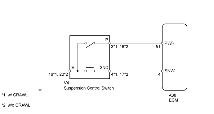
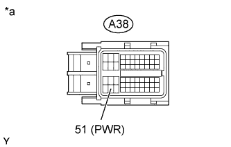
The ECM memory contains the programs for the normal and power shift patterns and lock-up pattern. By following the programs corresponding to the signals from the pattern select switch, the park/neutral position switch and other various sensors, the ECM switches the shift solenoid valves on and off, and controls the transmission gear change and the lock-up clutch operation.
WIRING DIAGRAM
INSPECTION PROCEDURE
When the pattern select (PWR) switch is pushed, switch contact is made and power mode is selected. To cancel power mode, push the pattern select (2nd) switch once again.
1. INSPECT PATTERN SELECT (PWR) SWITCH
Remove the suspension control switch (Click here).
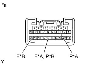
Measure the resistance according to the value(s) in the table below.
Standard Resistance:
w/ CRAWL
Tester Connection
Switch Condition
Specified Condition
3 (P) - 16 (E)
Pattern select (PWR) switch on
Below 1 Ω
3 (P) - 16 (E)
Pattern select (PWR) switch off
10 kΩ or higher
w/o CRAWL
Tester Connection
Switch Condition
Specified Condition
16 (P) - 20 (E)
Pattern select (PWR) switch on
Below 1 Ω
16 (P) - 20 (E)
Pattern select (PWR) switch off
10 kΩ or higher
Text in Illustration
A
w/ CRAWL
B
w/o CRAWL
*a
Component without harness connected (Suspension Control Switch)
NG
REPLACE PATTERN SELECT (PWR) SWITCH (SUSPENSION CONTROL SWITCH) (Click here)
OK
2. CHECK HARNESS AND CONNECTOR (PATTERN SELECT (PWR) SWITCH - BODY GROUND)
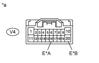
Disconnect the suspension control switch connector.
Measure the resistance according to the value(s) in the table below.
Standard Resistance:
w/ CRAWL
Tester Connection
Condition
Specified Condition
V4-16 (E) - Body ground
Always
Below 1 Ω
w/o CRAWL
Tester Connection
Condition
Specified Condition
V4-20 (E) - Body ground
Always
Below 1 Ω
Text in Illustration
A
w/ CRAWL
B
w/o CRAWL
*a
Front view of wire harness connector (to Suspension Control Switch)