Circuit diagnosis · Vehicles built Sep 2011 – Dec 2011
Versions by build date: Sep 2011 – Dec 2011from Jan 2012
DESCRIPTION
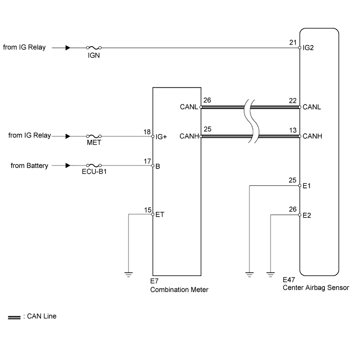
The SRS warning light is located on the combination meter. When the SRS is normal, the SRS warning light comes on for approximately 6 seconds after the ignition switch is turned from off to ON, and then goes off automatically. If there is a malfunction in the SRS, the SRS warning light comes on to inform the driver of a problem. When terminals TC and CG of the DLC3 are connected, DTCs are output by the blinking of the SRS warning light. The SRS is equipped with a voltage-increase circuit (DC-DC converter) in the center airbag sensor in case the source voltage drops. When the battery voltage drops, the voltage-increase circuit (DC-DC converter) functions to increase the voltage of the SRS to normal voltage. A malfunction in this circuit is not recorded in the center airbag sensor. The SRS warning light automatically goes off when the source voltage returns to normal. The signal to illuminate the SRS warning light is transmitted from the center airbag sensor to the combination meter through the CAN communication system.
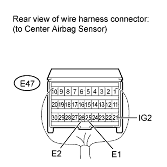
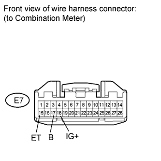
WIRING DIAGRAM
INSPECTION PROCEDURE
NOTICE:
When disconnecting the cable from the negative (-) battery terminal while performing repairs, some systems need to be initialized after the cable is reconnected (Click here).
1. CHECK CAN COMMUNICATION SYSTEM
Check if a CAN communication DTC is output.
Result
Result
Proceed to
DTC is not output
A
DTCs are output (for LHD)
B
DTCs are output (for RHD)
C
B
REPAIR CIRCUITS INDICATED BY OUTPUT DTCS (Click here)
C
REPAIR CIRCUITS INDICATED BY OUTPUT DTCS (Click here)