SYSTEM DESCRIPTION
Troubleshooting · Vehicles built Sep 2011 – Dec 2011
Versions by build date: Sep 2011 – Dec 2011 from Jan 2012
| OUTLINE |
- As a unique feature of the Rear Seat Entertainment (RSE) system, the rear seat occupants can enjoy different audio-visual modes at the same time.
- The rear seat occupants can control the audio-visual modes with the remote control, and listen to audio by using wired or wireless headphones.
- The television display assembly receives image and sound signals from the display and navigation module display.
- The rear seat occupants can enjoy watching video by connecting an external device.
- MOST communication is used between the display and navigation module display and the television display assembly.
- Occupants in the front seats and rear seats can enjoy different content at the same time.
| FUNCTION OF MAIN COMPONENTS |
| Component |
Function |
| Television Display Assembly |
|
| Radio Receiver Assembly |
|
| Remote Control |
Outputs various control signals of the RSE system to the television display assembly in the form of infrared signals. |
| Wireless Headphone |
|
| Headphone Terminal |
|
| Video Terminal |
This terminal is for connecting the video player's video and audio output terminals. |
| Display and Navigation Module Display |
Receives DVD image signals from the radio receiver assembly and sends the signals to the television display assembly. |
| COMMUNICATION SYSTEM |
MOST NETWORK OUTLINE
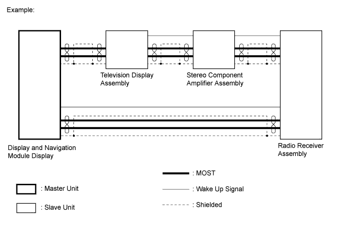

Navigation system components communicate with each other via the MOST network.
The MOST network uses a shielded twisted pair of wires for its communication lines.
The master unit of the MOST network is the display and navigation module display.
MOST communication lines connect each slave unit centering around the master unit to form a MOST network ring.
The master unit sends a wake-up signal to activate each slave unit connected to the MOST network.
- HINT:
- If a short or open circuit occurs in the MOST circuit, communication will be interrupted and the system will not operate normally.
AVC-LAN OUTLINE
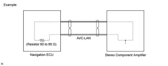
Components of the navigation system communicate with each other via the AVC-LAN.
The AVC-LAN uses a twisted pair of wires for its communication lines.
The master unit of the AVC-LAN is the display and navigation module display.
- HINT:
- The display and navigation module display has enough resistance (60 to 80 Ω) necessary for communication.
- If a short or open circuit occurs in the AVC-LAN circuit, communication is interrupted and system will not operate normally.
- The display and navigation module display has enough resistance (60 to 80 Ω) necessary for communication.
| DIAGNOSIS FUNCTION |
When the navigation system changes to the diagnosis screen, the television display assembly shows the "RSE Check" screen.
| Digital Versatile Disc (DVD) PLAYER OUTLINE |
The DVD player can only play DVD videos that have one of the following marks:

Precaution for use of discs
- NOTICE:
- Keep the discs away from dirt. Be careful not to damage the discs or leave your fingerprints on them.
- Hold discs by the outer edge and center hole with the label side up.
- Leaving the disc exposed halfway out of the slot for a long time after pressing the disc eject button may cause deformation of the disc, making the disc unusable.
- Do not use uniquely-shaped CDs because these may cause player malfunctions.
- Do not use discs whose recording portion is transparent or translucent because they may not be able to be inserted, ejected or played normally.
- Keep the discs away from dirt. Be careful not to damage the discs or leave your fingerprints on them.
Check disc
Check that the disc is not deformed or cracked.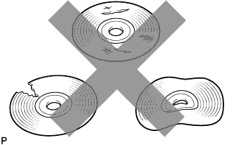
Disc cleaning
- NOTICE:
- Do not use a lens cleaner because it may cause a malfunction in the pickup portion of the player.
If dirt is on the disc surface, wipe it clean with a soft cloth from the inside to the outside in a radial direction.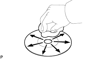
- NOTICE:
- Pressing on the disc by hand or rubbing the disc with a hard cloth may scratch the disc surface.
- Use of solvent such as a record spray, antistatic agent, alcohol, benzine, and thinner or a chemical cloth may cause damage to the disc, making the disc unusable.
- Pressing on the disc by hand or rubbing the disc with a hard cloth may scratch the disc surface.