REASSEMBLY
Removal / installation · Vehicles built from Sep 2011
| 1. INSTALL NO. 2 TRANSMISSION HUB SLEEVE |

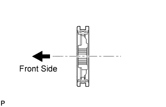  |
Apply a light coat of gear oil to the No. 2 transmission hub sleeve and No. 2 transmission clutch hub.
Install the No. 2 transmission hub sleeve and 3 shifting keys to the No. 2 transmission clutch hub.
- NOTICE:
- Do not mistake the installation direction of the No. 2 transmission hub sleeve and No. 2 transmission clutch hub.
Insert the 2 springs under the shifting keys.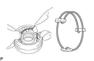
- NOTICE:
- Position the key springs so that their end gaps are not aligned.
| 2. INSTALL NO. 3 TRANSMISSION HUB SLEEVE |
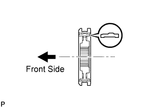 |
Apply a light coat of gear oil to the No. 3 transmission hub sleeve and No. 3 transmission clutch hub.
Install the No. 3 transmission hub sleeve and 3 shifting keys to the No. 3 transmission clutch hub.
- NOTICE:
- Do not mistake the installation direction of the No. 3 transmission hub sleeve, No. 3 transmission clutch hub, and shifting keys.
Insert the 2 springs under the shifting keys.
- NOTICE:
- Position the key springs so that their end gaps are not aligned.
| 3. INSTALL NO. 1 TRANSMISSION HUB SLEEVE |
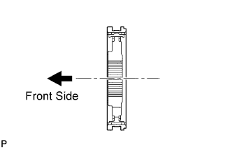 |
Apply a light coat of gear oil to the No. 1 transmission hub sleeve and No. 1 transmission clutch hub.
Install the No. 1 transmission hub sleeve and 3 shifting keys to the No. 1 transmission clutch hub.
- NOTICE:
- Do not mistake the installation direction of the No. 1 transmission hub sleeve and No. 1 transmission clutch hub.
Insert the 2 springs under the shifting keys.
- NOTICE:
- Position the key springs so that their end gaps are not aligned.
| 4. INSTALL 5TH COUNTER GEAR BEARING |
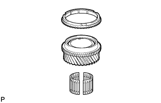 |
Coat the 5th counter gear bearing with gear oil, then install it to the 5th gear.
| 5. INSTALL 5TH GEAR |
Coat the 5th gear and No. 3 synchronizer ring with gear oil, and set them onto the output shaft.
Using SST and a press, install the 5th gear, No. 3 synchronizer ring and transmission hub sleeve to the output shaft.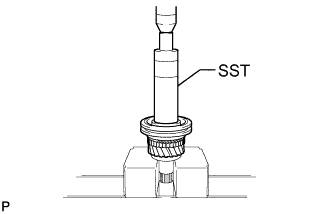
- SST
- 09316-60011
(09316-00011)
- HINT:
- Align the convex portion of the synchronizer ring with the groove of the transmission hub sleeve.
Check that the 5th gear, No. 3 synchronizer ring, and transmission hub sleeve move smoothly.
| 6. INSTALL NO. 3 TRANSMISSION CLUTCH HUB SHAFT SNAP RING |
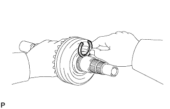 |
Select a new snap ring that will allow minimum clearance.
- Standard Clearance:
- 0.1 mm (0.00393 in.) or less
- Snap Ring Thickness:
Part No.
Thickness
Mark
90520-34018
2.40 to 2.45 mm
(0.0945 to 0.0965 in.)
A
90520-34019
2.45 to 2.50 mm
(0.0965 to 0.0984 in.)
B
90520-34020
2.50 to 2.55 mm
(0.0984 to 0.100 in.)
C
90520-34021
2.55 to 2.60 mm
(0.100 to 0.102 in.)
D
90520-34022
2.60 to 2.65 mm
(0.102 to 0.104 in.)
E
90520-34023
2.65 to 2.70 mm
(0.104 to 0.106 in.)
F
Using a brass bar and hammer, install the snap ring to the output shaft.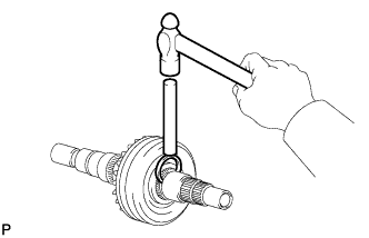
| 7. INSTALL 3RD GEAR NEEDLE ROLLER BEARING |
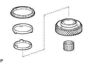 |
Coat the 3rd gear needle roller bearing with gear oil, and install it to the 3rd gear.
| 8. INSTALL 3RD GEAR |
Coat the 3rd gear and No. 3 synchronizer ring set with gear oil, and set them onto the output shaft.
- HINT:
- Align the protrusions of the middle ring of the synchronizer ring set with the notches of the gear.
Using SST and a press, install the 3rd gear, No. 3 synchronizer ring set and transmission hub sleeve to the output shaft.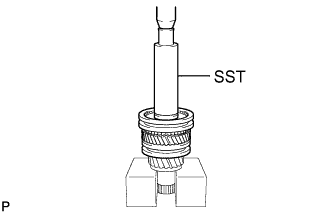
- SST
- 09316-60011
(09316-00011)
- HINT:
- Align the convex portion of the synchronizer ring with the groove of the transmission hub sleeve.
Check that the 3rd gear, No. 3 synchronizer ring set, and transmission hub sleeve move smoothly.
| 9. INSTALL NO. 2 CLUTCH HUB SETTING SHAFT SNAP RING |
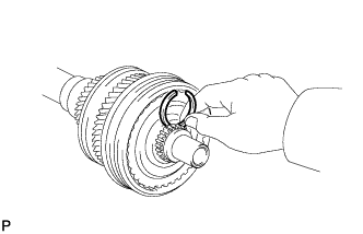 |
Select a new snap ring that will allow minimum clearance.
- Standard Clearance:
- 0.1 mm (0.00393 in.) or less
- Snap Ring Thickness:
Part No.
Thickness
Mark
90520-28054
1.90 to 1.95 mm
(0.0748 to 0.0768 in.)
4
90520-28055
1.95 to 2.00 mm
(0.0768 to 0.0787 in.)
5
90520-28056
2.00 to 2.05 mm
(0.0787 to 0.0807 in.)
6
90520-28057
2.05 to 2.10 mm
(0.0807 to 0.0827 in.)
7
90520-28058
2.10 to 2.15 mm
(0.0827 to 0.0847 in.)
8
90520-28059
2.15 to 2.20 mm
(0.0847 to 0.0866 in.)
9
Using a snap ring expander, install the snap ring to the output shaft.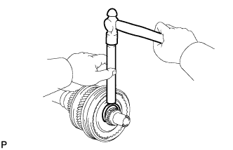
| 10. INSTALL 2ND GEAR NEEDLE ROLLER BEARING |
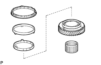 |
Coat the 2nd gear needle roller bearing with gear oil, and install it to the output shaft.
| 11. INSTALL 2ND GEAR |
Coat the 2nd gear and No. 2 synchronizer ring set with gear oil, then install them to the output shaft.
- HINT:
- Align the protrusions of the middle ring of the synchronizer ring set with the notches of the gear.
Using a press, install the 2nd gear, No. 2 synchronizer ring set and transmission hub sleeve to the output shaft.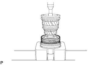
- HINT:
- Align the convex portion of the synchronizer ring with the groove of the transmission hub sleeve.
Check that the 2nd gear, No. 2 synchronizer ring set, and transmission hub sleeve move smoothly.
| 12. INSTALL NO. 1 CLUTCH HUB SHAFT SNAP RING |
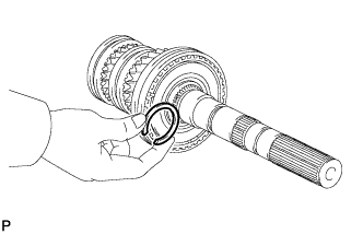 |
Select a new snap ring that will allow minimum clearance.
- Standard Clearance:
- 0.1 mm (0.00393 in.) or less
- Snap Ring Thickness:
Part No.
Thickness
Mark
90520-46004
2.90 to 2.95 mm
(0.114 to 0.116 in.)
A
90520-46005
2.95 to 3.00 mm
(0.116 to 0.118 in.)
B
90520-46006
3.00 to 3.05 mm
(0.118 to 0.120 in.)
C
90520-46007
3.05 to 3.10 mm
(0.120 to 0.122 in.)
D
90520-46008
3.10 to 3.15 mm
(0.122 to 0.124 in.)
E
90520-46009
3.15 to 3.20 mm
(0.124 to 0.126 in.)
F
Using a brass bar and a hammer, install the snap ring to the output shaft.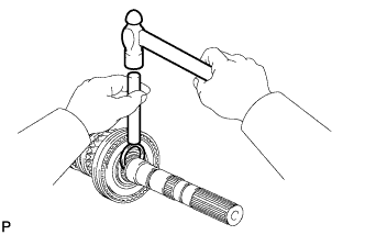
| 13. INSTALL 1ST GEAR NEEDLE ROLLER BEARING |
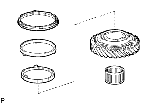 |
Coat the 1st gear needle roller bearing with gear oil, and install it to the output shaft.
| 14. INSTALL 1ST GEAR |
Coat the 1st gear and No. 1 synchronizer ring set with gear oil, and set them onto the output shaft.
- HINT:
- Align the protrusions of the middle ring of the synchronizer ring set with the notches of the gear.
Using SST and press, install the 1st gear, No. 1 synchronizer ring set, and output shaft rear bearing to the output shaft.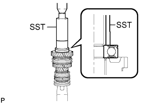
- SST
- 09316-60011
(09316-00011)
09523-36010
- HINT:
- Make sure that the groove of the bearing faces the correct direction as shown in the illustration.
- Align the convex portion of the synchronizer ring with the groove of the transmission hub sleeve.
- Make sure that the groove of the bearing faces the correct direction as shown in the illustration.
Check that the transmission hub sleeve, 1st gear and No. 1 synchronizer ring set move smoothly.
| 15. INSTALL REVERSE GEAR SNAP RING |
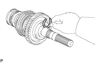 |
Select a new snap ring that will allow minimum clearance.
- Standard Clearance:
- 0.1 mm (0.00393 in.) or less
- Snap Ring Thickness:
Part No.
Thickness
Mark
90520-41006
2.40 to 2.45 mm
(0.0945 to 0.0965 in.)
A
90520-41007
2.45 to 2.50 mm
(0.0965 to 0.0984 in.)
B
90520-41008
2.50 to 2.55 mm
(0.0984 to 0.100 in.)
C
90520-41009
2.55 to 2.60 mm
(0.100 to 0.102 in.)
D
90520-41010
2.60 to 2.65 mm
(0.102 to 0.104 in.)
E
90520-41011
2.65 to 2.70 mm
(0.104 to 0.106 in.)
F
90520-41012
2.70 to 2.75 mm
(0.106 to 0.108 in.)
G
90520-41013
2.75 to 2.80 mm
(0.108 to 0.110 in.)
H
Using a brass bar and a hammer, install the snap ring to the output shaft.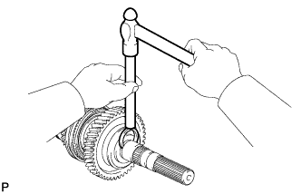
| 16. INSPECT 5TH GEAR THRUST CLEARANCE |
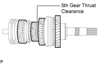 |
Using a feeler gauge, measure the 5th gear thrust clearance.
- Standard Clearance:
- 0.10 to 0.35 mm (0.00394 to 0.0137 in.)
| 17. INSPECT 3RD GEAR THRUST CLEARANCE |
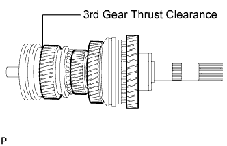 |
Using a feeler gauge, measure the 3rd gear thrust clearance.
- Standard Clearance:
- 0.10 to 0.45 mm (0.00394 to 0.0177 in.)
| 18. INSPECT 2ND GEAR THRUST CLEARANCE |
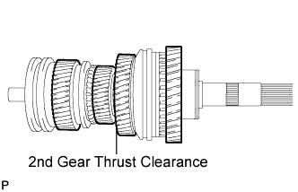 |
Using a feeler gauge, measure the 2nd gear thrust clearance.
- Standard Clearance:
- 0.10 to 0.35 mm (0.00394 to 0.0137 in.)
| 19. INSPECT 1ST GEAR THRUST CLEARANCE |
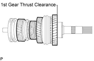 |
Using a feeler gauge, measure the 1st gear thrust clearance.
- Standard Clearance:
- 0.10 to 0.45 mm (0.00394 to 0.0177 in.)
| 20. INSPECT 5TH GEAR RADIAL CLEARANCE |
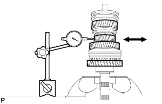 |
Using a dial indicator, measure the 5th gear radial clearance.
- Standard Clearance:
- 0.015 to 0.068 mm (0.000591 to 0.00267 in.)
| 21. INSPECT 3RD GEAR RADIAL CLEARANCE |
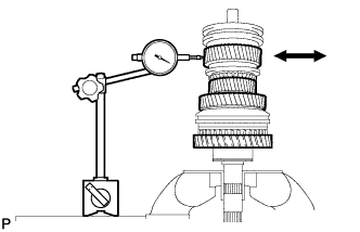 |
Using a dial indicator, measure the 3rd gear radial clearance.
- Standard Clearance:
- 0.020 to 0.073 mm (0.000788 to 0.00287 in.)
| 22. INSPECT 2ND GEAR RADIAL CLEARANCE |
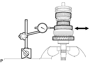 |
Using a dial indicator, measure the 2nd gear radial clearance.
- Standard Clearance:
- 0.015 to 0.068 mm (0.000591 to 0.00267 in.)
| 23. INSPECT 1ST GEAR RADIAL CLEARANCE |
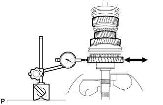 |
Using a dial indicator, measure the 1st gear radial clearance.
- Standard Clearance:
- 0.020 to 0.073 mm (0.000788 to 0.00287 in.)