SYSTEM DIAGRAM
System information · Vehicles built from Jan 2012
Versions by build date: Sep 2011 – Dec 2011 from Jan 2012
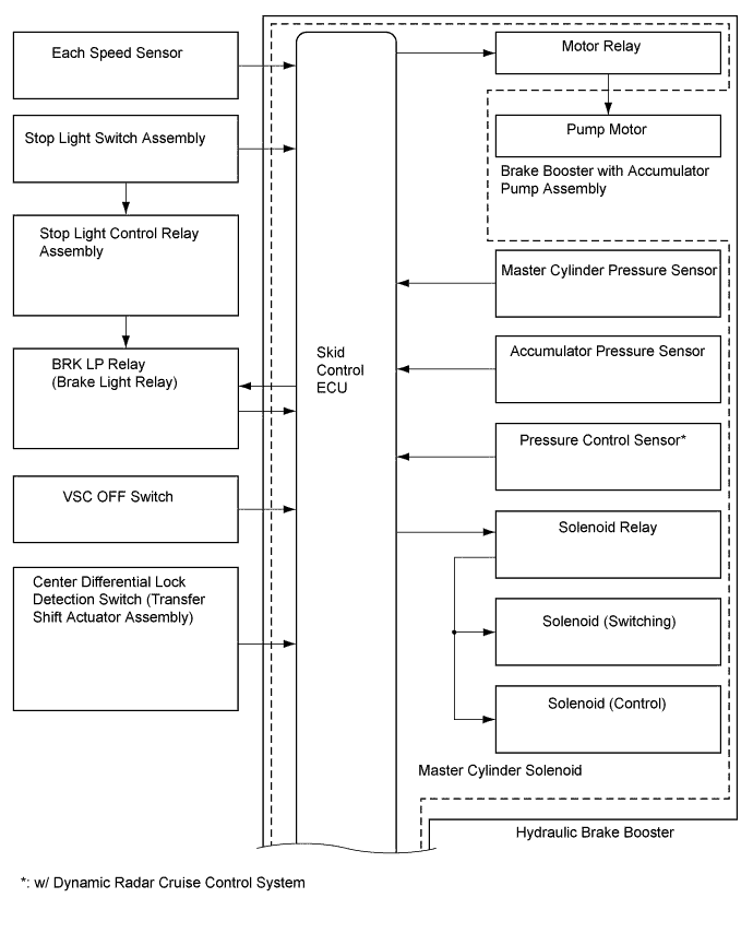

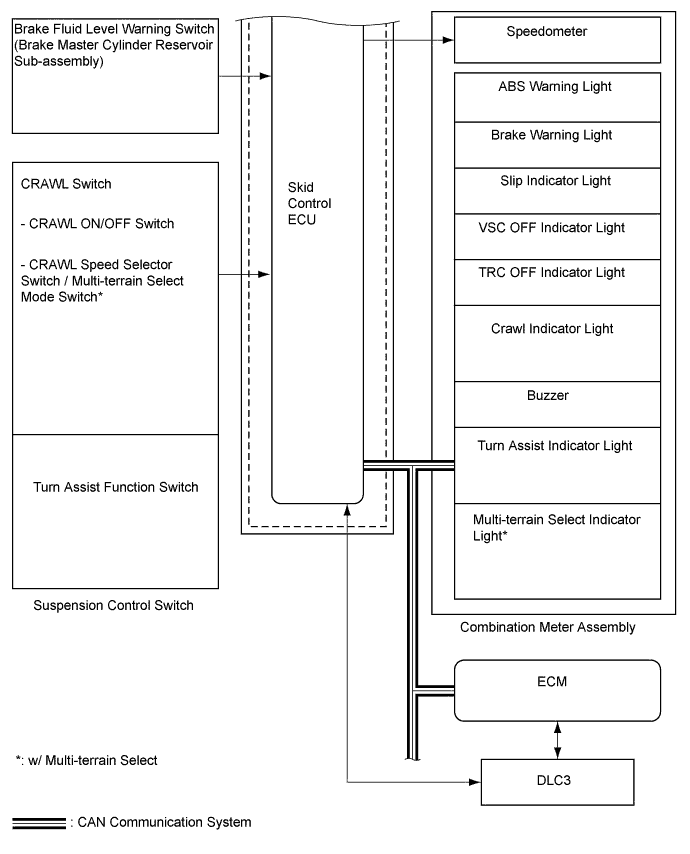
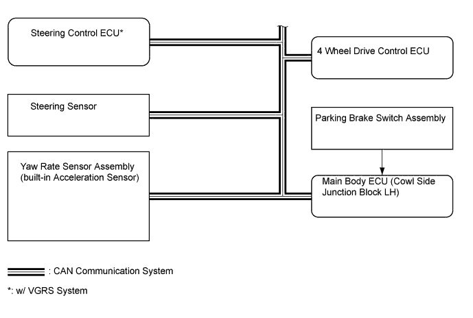
| Sender |
Receiver |
Signal |
Line |
| ECM |
Skid control ECU |
|
CAN communication |
| Skid control ECU |
ECM |
|
CAN communication |
| Skid control ECU |
Combination meter |
|
CAN communication |
| 4 wheel drive control ECU |
Skid control ECU |
L4 status signal |
CAN communication |
| Steering sensor |
Skid control ECU |
Steering angle signal |
CAN communication |
| Steering control ECU (*) |
Skid control ECU |
Variable gear ratio signal |
CAN communication |
- *: w/ VGRS System