Removal / installation · Vehicles built Sep 2011 – Dec 2011
1.
DISCONNECT CABLE FROM NEGATIVE BATTERY TERMINAL
CAUTION:
Wait at least 90 seconds after disconnecting the cable from the negative (-) battery terminal to disable the SRS system.
NOTICE:
When disconnecting the cable, some systems need to be initialized after the cable is reconnected (Click here).
2.
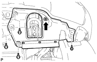
REMOVE FRONT FENDER SPLASH SHIELD SUB-ASSEMBLY LH
Remove the 3 bolts and screw.
Turn the clip indicated by the arrow in the illustration to remove the fender splash shield.
3.
REMOVE FRONT FENDER SPLASH SHIELD SUB-ASSEMBLY RH
HINT:
Use the same procedures described for the LH side.
4.
REMOVE NO. 1 ENGINE UNDER COVER SUB-ASSEMBLY
Remove the 10 bolts and No. 1 engine under cover.
5.
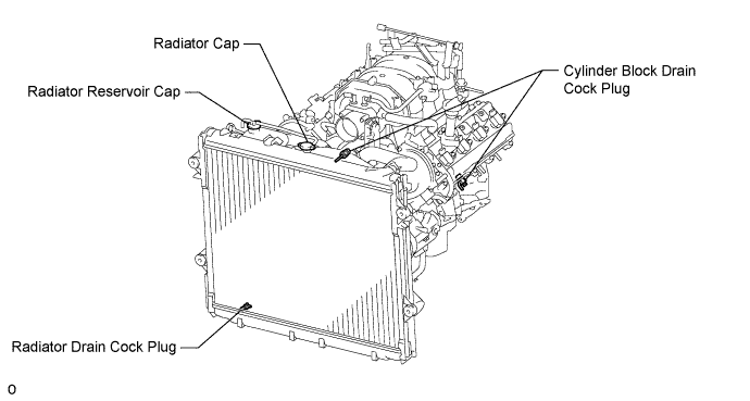
DRAIN ENGINE COOLANT
CAUTION:
Do not remove the radiator cap while the engine and radiator are still hot. Pressurized, hot engine coolant and steam may be released and cause serious burns.
Loosen the radiator drain cock plug.
Remove the radiator cap. Then drain the coolant.
HINT:
Collect the coolant in a container and dispose of it according to the regulations in your area.
Loosen the 2 cylinder block drain cock plugs. Then drain the coolant from the engine.
Tighten the 2 cylinder block drain cock plugs.
Torque:
13 N*m{
130 kgf*cm
, 9 ft.*lbf
}
Tighten the radiator drain cock plug by hand.
6.
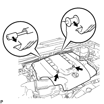
REMOVE V-BANK COVER SUB-ASSEMBLY
Remove the 2 nuts and V-bank cover.
7.
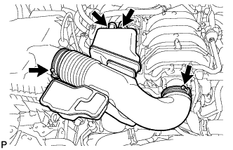
REMOVE AIR CLEANER HOSE ASSEMBLY
Disconnect the vacuum transmitting hose and No. 2 ventilation hose.
Loosen the 2 hose clamps.
Remove the air cleaner hose.
8.
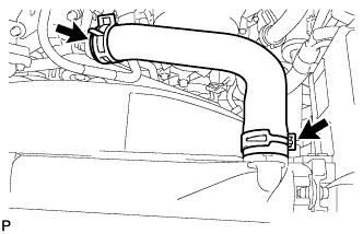
REMOVE NO. 1 RADIATOR HOSE
Using needle-nose pliers, grip the claws of the clamps and slide the clamps to remove the radiator hose.
9.
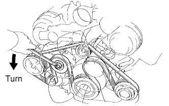
REMOVE FAN & GENERATOR V BELT
Loosen the belt tension by turning the belt tensioner counterclockwise, and then remove the fan and generator V belt.
HINT:
The pulley bolt for the belt tensioner has left-hand thread.
10.
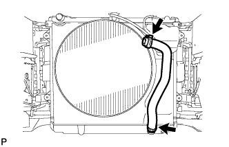
REMOVE NO. 2 RADIATOR HOSE
Using needle-nose pliers, grip the claws of the clamps and slide the clamps to remove the radiator hose.
11.
REMOVE FAN SHROUD
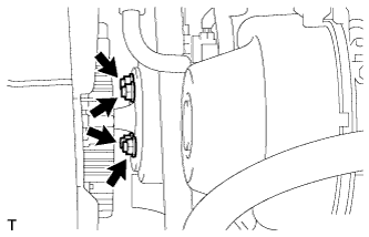
Loosen the 4 nuts holding the cooling fan.
Disconnect the reservoir hose from the upper side of the radiator tank.
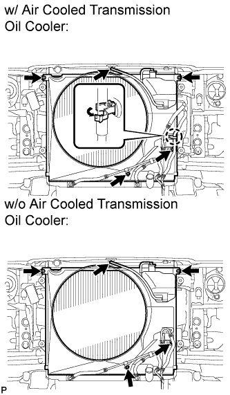
w/ Air Cooled Transmission Oil Cooler: Detach the claw to open the flexible hose clamp.
Remove the 2 bolts and disconnect the oil cooler tube from the fan shroud.
Remove the 2 bolts holding the fan shroud.
Remove the 4 nuts of the cooling fan, and then remove the shroud together with the cooling fan.
NOTICE:
Be careful not to damage the radiator core.
Remove the fan pulley from the water pump.
12.
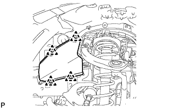
REMOVE FRONT FENDER APRON SEAL LH
Using a clip remover, remove the 4 clips and fender apron seal.
13.
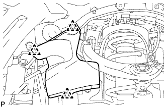
REMOVE FRONT FENDER APRON SEAL LH (w/ KDSS)
Using a clip remover, remove the 3 clips and fender apron seal.
14.
REMOVE FRONT FENDER APRON SEAL FRONT RH
Using a clip remover, remove the 3 clips and fender apron seal.
15.
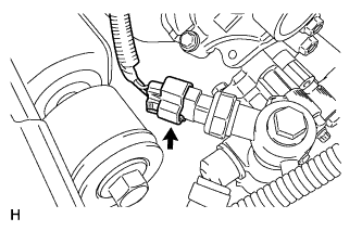
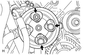
DISCONNECT COOLER COMPRESSOR ASSEMBLY
Disconnect the connector.
Remove the bolt. Then disconnect the cooler refrigerant suction hose from the cylinder head cover.
Remove the 3 bolts, nut and No. 1 compressor stay and disconnect the cooler compressor.
16.
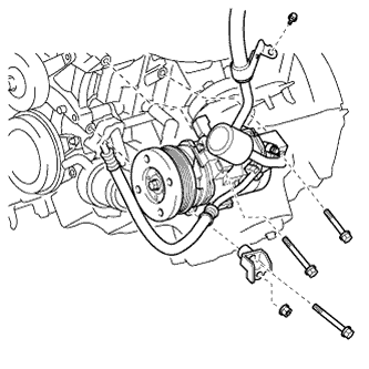
DISCONNECT VANE PUMP ASSEMBLY
Disconnect the connector.
Remove the 2 bolts and nut. Then disconnect the vane pump.
17.
REMOVE GENERATOR ASSEMBLY
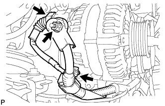
Disconnect the generator connector.
Remove the terminal cap and nut, and disconnect the generator wire.
Remove the bolt and disconnect the wire harness bracket from the generator.
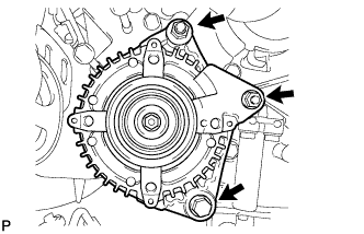
Remove the bolt, 2 nuts and generator.
18.
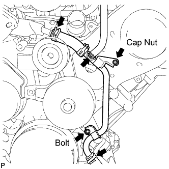
REMOVE OIL COOLER PIPE
Remove the cap nut and bolt.
Using needle-nose pliers, grip the claws of the clamps and slide the clamps to disconnect the 3 water by-pass hoses and remove the oil cooler pipe.
19.
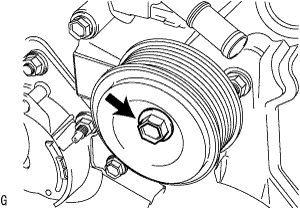
REMOVE NO. 2 IDLER PULLEY SUB-ASSEMBLY
Remove the pulley bolt, cover plate and idler pulley.
20.
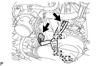
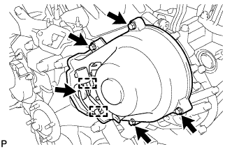
REMOVE NO. 3 TIMING BELT COVER SUB-ASSEMBLY LH
Detach the 3 wire clamps and disconnect the camshaft timing oil control valve connector and control motor connector.
Disconnect the camshaft position sensor connector.
Disconnect the camshaft position sensor wire from the 2 wire clamps on the timing belt cover.
Remove the wire grommet from the timing belt cover.
Remove the 4 bolts.
Pull the cover outward, pull the camshaft position sensor wire out of the cover, and remove the cover.
21.
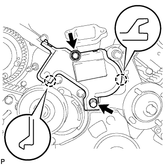
REMOVE NO. 3 TIMING BELT COVER SUB-ASSEMBLY RH
Remove the 3 bolts, nut and timing belt cover.
22.
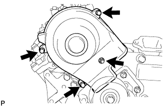
REMOVE NO. 2 TIMING BELT COVER SUB-ASSEMBLY
Remove the 2 bolts and detach the 2 claws, and then remove the No. 2 timing belt cover.
23.
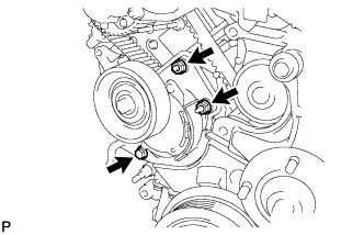
REMOVE V-RIBBED BELT TENSIONER ASSEMBLY
Remove the bolt, 2 nuts and V-ribbed belt tensioner.
24.
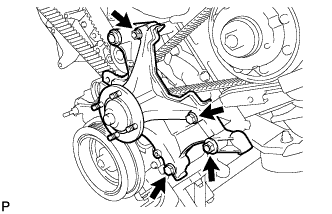
REMOVE FAN BRACKET SUB-ASSEMBLY
Remove the 2 nuts, 2 bolts and fan bracket.
25.
REMOVE CRANKSHAFT DAMPER SUB-ASSEMBLY
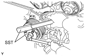
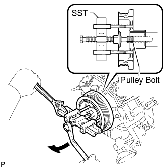
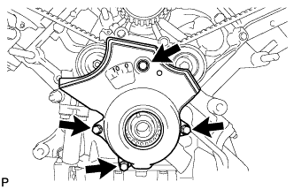
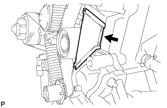
Using SST, hold the crankshaft damper and loosen the pulley bolt. Further loosen the bolt until 2 or 3 threads are screwed into the crankshaft.
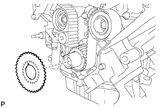
Remove the position sensor plate from the crankshaft.
29.
SET NO. 1 CYLINDER TO TDC/COMPRESSION
Temporarily install the pulley bolt.
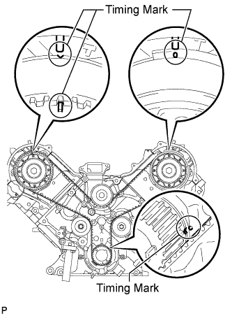
Rotate the crankshaft clockwise so that the timing marks on the crankshaft timing pulley and camshaft timing pulleys are as shown in the illustration.
HINT:
If the timing marks do not align, rotate the crankshaft clockwise again and align the timing marks.
When reusing the timing belt, put a timing mark on the belt where the timing marks on the belt and timing pulley are aligned after rotating the crankshaft.
30.
REMOVE TIMING BELT
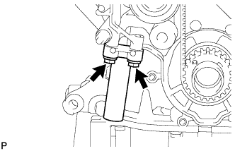
Alternately loosen the 2 bolts, then remove the bolts, timing belt tensioner and dust seal.
Remove the timing belt.
31.
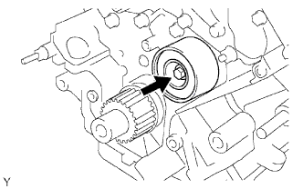
REMOVE NO. 1 TIMING BELT IDLER SUB-ASSEMBLY
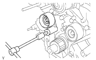
Using a 10 mm hexagon wrench, remove the idler shaft, timing belt idler and plate washer.