INSTALLATION
Removal / installation · Vehicles built Sep 2011 – Dec 2011
Versions by build date: Sep 2011 – Dec 2011 from Jan 2012
| 1. INSTALL POWER STEERING OIL PRESSURE SWITCH |

Install a new O-ring to the oil pressure switch.
Apply a light coat of engine oil to the O-ring of the oil pressure switch.
- NOTICE:
- When reusing the oil pressure switch, inspect the O-ring.
- If the O-ring has scratches or cuts, replace the new O-ring.
- When reusing the oil pressure switch, inspect the O-ring.
Using a 24 mm deep socket wrench, install the oil pressure switch.
- Torque:
- 21 N*m{ 214 kgf*cm , 15 ft.*lbf }
Connect the oil pressure switch connector.
| 2. INSTALL FAN AND GENERATOR V BELT |
Set the V belt onto every part.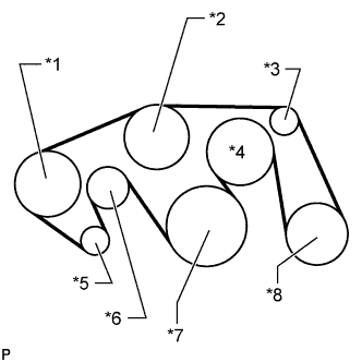

While turning the belt tensioner counterclockwise, remove the bar.
Text in Illustration *1
Vane Pump
*2
Water Pump
*3
No. 1 Idler
*4
Fan
*5
Generator
*6
Belt Tensioner
*7
Crankshaft
*8
Cooler Compressor
- NOTICE:
- Make sure that the V belt is properly set to each pulley.
After installing the belt, check that it fits properly in the ribbed grooves.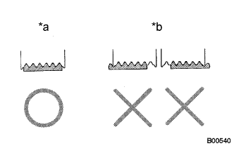
Text in Illustration *a
CORRECT
*b
INCORRECT
- HINT:
- Make sure to check by hand that the belt has not slipped out of the grooves on the bottom of the pulley.
| 3. INSTALL AIR CLEANER ASSEMBLY |
Install the air cleaner with the 3 bolts.
- Torque:
- 5.0 N*m{ 51 kgf*cm , 44 in.*lbf }
| 4. INSTALL AIR CLEANER HOSE ASSEMBLY |
Install the air cleaner hose so that the protrusion of the air cleaner cap aligns with the groove of the hose as shown in the illustration.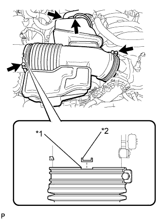
Text in Illustration *1
Groove
*2
Protrusion
Tighten the 2 clamps.
- Torque:
- 5.0 N*m{ 51 kgf*cm , 44 in.*lbf }
Connect the vacuum hose.
Connect the No. 2 ventilation hose.
| 5. ADD POWER STEERING FLUID |
| 6. BLEED POWER STEERING FLUID |
Check the fluid level.
Jack up the front of the vehicle and support it with stands.
Turn the steering wheel.
With the engine stopped, turn the wheel slowly from lock to lock several times.
Lower the vehicle.
Start the engine.
Idle the engine for a few minutes.
Turn the steering wheel.
With the engine idling, turn the wheel left or right to the full lock position and keep it there for 2 to 3 seconds, then turn the wheel to the opposite full lock position and keep it there for 2 to 3 seconds. *1
Repeat *1 several times.
- NOTICE:
- For vehicles with VGRS, if the steering wheel is turned from lock to lock repeatedly, the system may stop operating and the amount of rotation before the steering wheel locks may increase due to operation of the overheating prevention function. When the system temperature drops, the system operation automatically returns to normal.
Stop the engine.
Check for foaming or emulsification.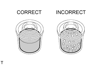
If the system has to be bled twice because of foaming or emulsification, check for fluid leaks in the system.
Check the fluid level.
| 7. INSPECT FOR POWER STEERING FLUID LEAK |
| 8. INSTALL FRONT FENDER APRON SEAL FRONT RH |
Install the fender apron seal with the 3 clips.
| 9. INSTALL FRONT WHEEL |
| 10. INSTALL V-BANK COVER SUB-ASSEMBLY |
Attach the 2 V-bank cover hooks to the bracket. Then align the 3 V-bank cover grommets with the 3 pins, and press down on the V-bank cover to attach the pins.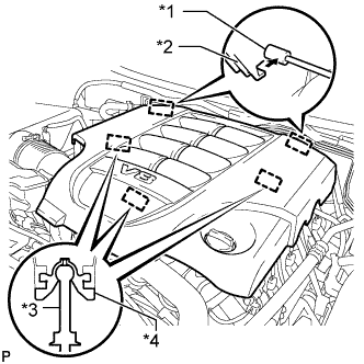
Text in Illustration *1
Bracket
*2
Hook
*3
Pin
*4
Grommet
| 11. INSTALL NO. 1 ENGINE UNDER COVER SUB-ASSEMBLY |
Install the No. 1 engine under cover with the 10 bolts.
- Torque:
- 29 N*m{ 296 kgf*cm , 21 ft.*lbf }
| 12. INSTALL FRONT FENDER SPLASH SHIELD SUB-ASSEMBLY LH |
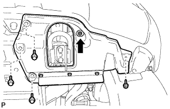 |
Push in the clip indicated by the arrow in the illustration to install the fender splash shield.
Install the 3 bolts and screw.
| 13. INSTALL FRONT FENDER SPLASH SHIELD SUB-ASSEMBLY RH |
- HINT:
- Use the same procedures described for the LH side.