INSTALLATION
Removal / installation · Vehicles built Sep 2011 – Dec 2011
Versions by build date: Sep 2011 – Dec 2011 from Jan 2012
| 1. INSTALL FUEL PRESSURE REGULATOR ASSEMBLY |

Apply a light coat of gasoline or spindle oil to a new O-ring, and install it to the pressure regulator.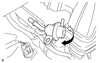

- NOTICE:
- Make sure that there are no scratches or foreign matter in or around the insertion hole of the delivery pipe.
- When inserting the injector, be careful not to damage the O-ring.
- Make sure that there are no scratches or foreign matter in or around the insertion hole of the delivery pipe.
While turning the pressure regulator left and right, install it to the delivery pipe.
Install the 2 bolts.
- Torque:
- 10 N*m{ 102 kgf*cm , 7 ft.*lbf }
Connect the vacuum sensing hose to the pressure regulator.
Connect the No. 2 fuel tube to the pressure regulator (Click here).
| 2. INSTALL AIR CLEANER HOSE ASSEMBLY |
Install the air cleaner hose so that the protrusion of the air cleaner cap aligns with the groove of the hose as shown in the illustration.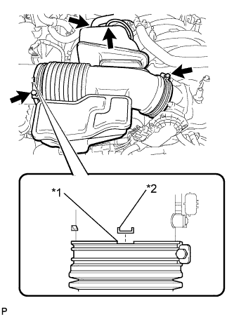
Text in Illustration *1
Groove
*2
Protrusion
Tighten the 2 clamps.
- Torque:
- 5.0 N*m{ 51 kgf*cm , 44 in.*lbf }
Connect the vacuum hose.
Connect the No. 2 ventilation hose.
| 3. INSTALL V-BANK COVER SUB-ASSEMBLY |
Attach the 2 V-bank cover hooks to the bracket. Then align the 3 V-bank cover grommets with the 3 pins, and press down on the V-bank cover to attach the pins.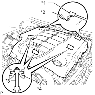
Text in Illustration *1
Bracket
*2
Hook
*3
Pin
*4
Grommet
| 4. CONNECT CABLE TO NEGATIVE BATTERY TERMINAL |
- NOTICE:
- When disconnecting the cable, some systems need to be initialized after the cable is reconnected (Click here).
| 5. INSPECT FOR FUEL LEAK |
Connect the intelligent tester to the DLC3.
Turn the engine switch on (IG) and intelligent tester main switch on.
- NOTICE:
- Do not start the engine.
Enter the following menus: Powertrain / Engine and ECT / Active Test / Control the Fuel Pump / Speed.
Check that there are no fuel leaks after doing maintenance anywhere on the fuel system.