REMOVAL
Removal / installation · Vehicles built from Jan 2012
| 1. REMOVE COOLER COMPRESSOR ASSEMBLY |

| 2. REMOVE FRONT FENDER SPLASH SHIELD SUB-ASSEMBLY LH |
Remove the 3 bolts and screw.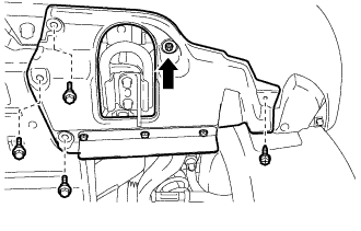

Turn the clip indicated by the arrow in the illustration to remove the front fender splash shield sub-assembly LH.
| 3. REMOVE FRONT FENDER SPLASH SHIELD SUB-ASSEMBLY RH |
Remove the 3 bolts and 2 screws.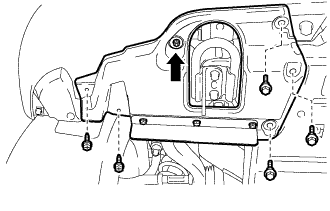
Turn the clip indicated by the arrow in the illustration to remove the front fender splash shield sub-assembly RH.
| 4. REMOVE NO. 1 ENGINE UNDER COVER SUB-ASSEMBLY |
Remove the 10 bolts and No. 1 engine under cover sub-assembly.
| 5. DRAIN ENGINE COOLANT |
- CAUTION:
- Do not remove the radiator cap while the engine and radiator are still hot. Pressurized, hot engine coolant and steam may be released and cause serious burns.
Loosen the radiator drain cock plug.
Remove the radiator cap and drain the coolant.
- HINT:
- Collect the coolant in a container and dispose of it according to the regulations in your area.
Loosen the 2 cylinder block drain cock plugs and drain the coolant from the engine.
Tighten the 2 cylinder block drain cock plugs.
- Torque:
- 13 N*m{ 130 kgf*cm , 9 ft.*lbf }
Tighten the radiator drain cock plug by hand.
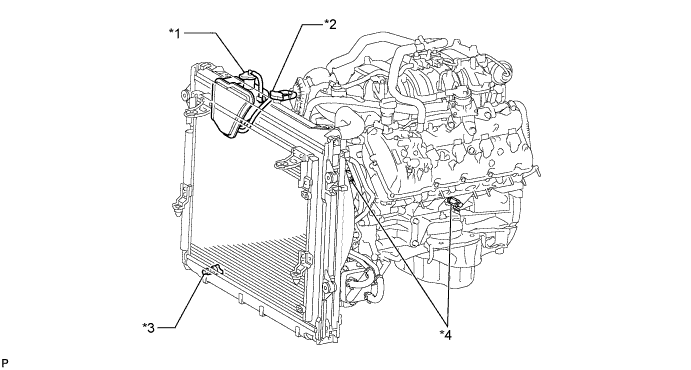
Text in Illustration *1
Reservoir Cap
*2
Radiator Cap
*3
Radiator Drain Cock Plug
*4
Cylinder Block Drain Cock Plug
| 6. REMOVE V-BANK COVER SUB-ASSEMBLY |
Raise the front of the V-bank cover to detach the 3 pins. Then remove the 2 V-bank cover hooks from the bracket, and remove the V-bank cover.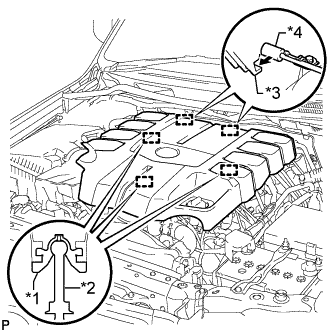
Text in Illustration *1
Grommet
*2
Pin
*3
Hook
*4
Bracket
| 7. REMOVE AIR CLEANER CAP AND HOSE |
Disconnect the No. 2 PCV hose and No. 1 air hose.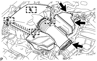
Disconnect the mass air flow meter connector and detach the clamp.
Detach the 4 clamps.
Loosen the hose clamp and remove the air cleaner cap and hose.
| 8. REMOVE NO. 1 RADIATOR HOSE |
Remove the No. 1 radiator hose.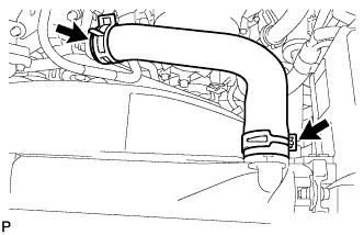
| 9. REMOVE FAN SHROUD |
Loosen the 4 nuts holding the fluid coupling fan.
Remove the fan and generator V-belt (Click here).
Disconnect the reservoir hose from the upper radiator tank.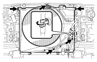
w/ Air Cooled Transmission Oil Cooler:
Detach the claw to open the flexible hose clamp.
Remove the 2 bolts and disconnect the oil cooler tube from the fan shroud.
Remove the 2 bolts holding the fan shroud.
Remove the 4 nuts of the fluid coupling fan, and then remove the shroud together with the fluid coupling fan.
- NOTICE:
- Be careful not to damage the radiator core.
Remove the fan pulley from the engine water pump.
| 10. REMOVE NO. 2 RADIATOR HOSE |
Remove the No. 2 radiator hose.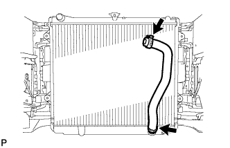
| 11. REMOVE AIR TUBE SUB-ASSEMBLY (w/ Secondary Air Injection System) |
Disconnect the No. 2 air injection system hose from the air switching valve.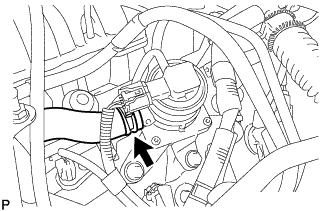
Disconnect the manifold absolute pressure sensor connector and detach the clamp.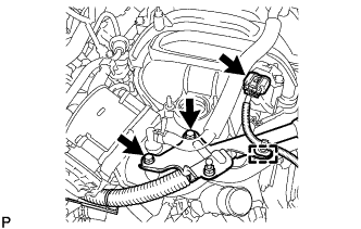
Remove the 2 bolts and bracket.
Remove the bolt and air tube.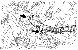
| 12. DISCONNECT WATER BY-PASS HOSE |
Disconnect the water by-pass hose.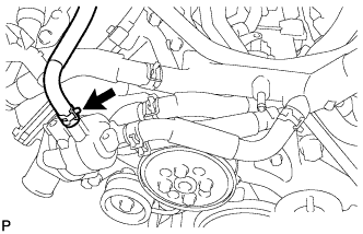
| 13. REMOVE NO. 1 WATER BY-PASS HOSE |
Remove the No. 1 water by-pass hose.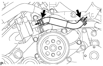
| 14. REMOVE NO. 2 WATER BY-PASS PIPE SUB-ASSEMBLY |
Remove the 2 bolts.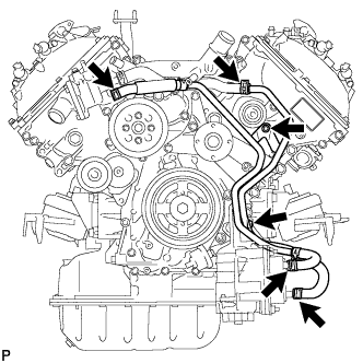
Disconnect the 4 hoses and remove the No. 2 water by-pass pipe.
| 15. DISCONNECT NO. 5 WATER BY-PASS HOSE |
Disconnect the No. 5 water by-pass hose.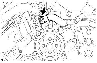
| 16. REMOVE WATER INLET HOUSING |
Remove the 3 bolts and water inlet housing.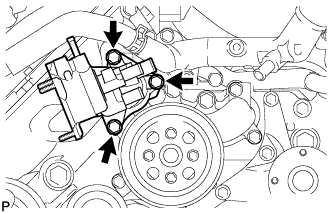
Remove the gasket from the engine water pump.
| 17. REMOVE WATER PUMP PULLEY |
Using SST, hold the water pump pulley.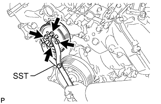
- SST
- 09960-10010
(09962-01000, 09963-01000)
Remove the 4 bolts and water pump pulley.
| 18. REMOVE ENGINE WATER PUMP ASSEMBLY |
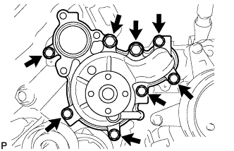
Remove the 8 bolts, engine water pump and gasket.