Sound Signal Circuit between Radio Receiver and Multi-media Interface ECU
Circuit diagnosis · Vehicles built Sep 2011 – Dec 2011
Versions by build date: Sep 2011 – Dec 2011 from Jan 2012
DESCRIPTION
The multi-media interface ECU sends sound signals to the radio receiver assembly through this circuit.If there is an open or short in the circuit, sound cannot be heard from the speakers even if there is no malfunction in the stereo component amplifier assembly, radio receiver assembly or speakers.
WIRING DIAGRAM
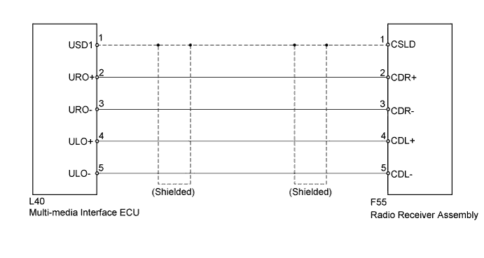

INSPECTION PROCEDURE
| 1. CHECK HARNESS AND CONNECTOR (RADIO RECEIVER ASSEMBLY - MULTI-MEDIA INTERFACE ECU) |

Disconnect the F55 radio receiver assembly and L40 multi-media interface ECU connectors.
Measure the resistance according to the value(s) in the table below.
- Standard Resistance:
Tester Connection
Condition
Specified Condition
L40-1 (USD1) - F55-1 (CSLD)
Always
Below 1 Ω
L40-2 (URO+) - F55-2 (CDR+)
Always
Below 1 Ω
L40-3 (URO-) - F55-3 (CDR-)
Always
Below 1 Ω
L40-4 (ULO+) - F55-4 (CDL+)
Always
Below 1 Ω
L40-5 (ULO-) - F55-5 (CDL-)
Always
Below 1 Ω
L40-1 (USD1) - Body ground
Always
10 kΩ or higher
L40-2 (URO+) - Body ground
Always
10 kΩ or higher
L40-3 (URO-) - Body ground
Always
10 kΩ or higher
L40-4 (ULO+) - Body ground
Always
10 kΩ or higher
L40-5 (ULO-) - Body ground
Always
10 kΩ or higher
|
|
||||

| OK | ||
 |
||
| ||